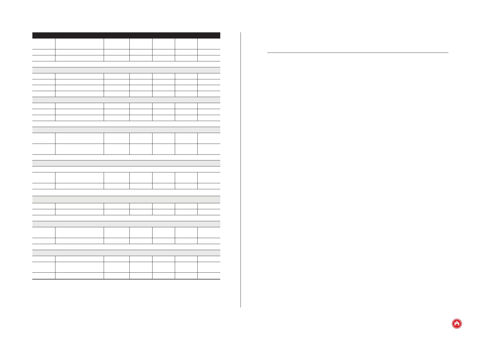
(APPENDIX III) DIMENSIONS, WIRING AND MECHANICAL PARTS | PAGE 96
Signal Description Type Characteristics
P Oil pressure Input
Analogue input of resistance
sensor VDO
T Coolant temperature Input
Analogue input of resistance
sensor VDO
Anc Auxiliary analogue Input
Analogue input of resistance
sensor VDO
DI Alternator voltage Input
Analogue input with voltage
0-40V
COM
Common analogue
inputs
Input VDO mass sensors
Digital outputs 1A
D+
Battery charging
alternator
Output PNP digital output
AL Alarm Output PNP digital output
MA Engine started Output PNP digital output
SAL1 Auxiliary output 1 Output PNP digital output
SAL2 Auxiliary output 2 Output PNP digital output
SAL3 Auxiliary output 3 Output PNP digital output
Digital outputs 40A
+BAT
Positive battery
terminal
Power supply Digital outputs supply voltage
ARR Start-up Output PNP digital output
PR Preheating Output PNP digital output
PC Congurable stop Output PNP digital output
Genset three-phase current inputs
IL3 T-phase current Input
Analogue input for current
measurement
IL2 S-phase current Input
Analogue input for current
measurement
IL1 R-phase current Input
Analogue input for current
measurement
ILN Neutral current Input
Analogue input for current
measurement
INPUTS AND OUTPUTS
Signal Description Type Characteristics
8÷36V Positive power supply Power supply
Module supply voltage from 8
to 36 V
-BAT Negative power supply Power supply Module supply negative
MAN Manual Input Start up PNP digital input
CAN Bus
CANS CAN bus screen CAN Bus CAN communication
CANL L signal of CAN bus CAN Bus CAN communication
CANH H signal of CAN bus CAN Bus CAN communication
J1939 Bus (CAN ECU engine)
J1939S J1939 bus screen J1939 Bus J1939 communication
J1939L J1939 Bus L signal J1939 Bus J1939 communication
J1939H J1939 Bus H signal J1939 Bus J1939 communication
Digital inputs
RC Fuel reserve Input NPN digital input
BPA Low oil pressure Input NPN digital input
ATA
High water temper-
ature
Input NPN digital input
NA Low water level Input NPN digital input
ENT4 Auxiliary input 4 Input NPN digital input
ENT5 Auxiliary input 5 Input NPN digital input
PEM Emergency Stop Input NPN digital input
ENT1 Auxiliary input 1 Input NPN digital input
ENT2 Auxiliary input 2 Input NPN digital input
ENT3 Auxiliary input 3 Input NPN digital input
SETA Emergency stop button Input NPN digital input
Pick-up input
PCK1 Pick-up 1 Input Pick-up input
PCK2 Pick-up 2 Input Pick-up input
Analogue inputs
NC Fuel level Input
Analogue input of resistance
sensor VDO