60
Connecting the Cables
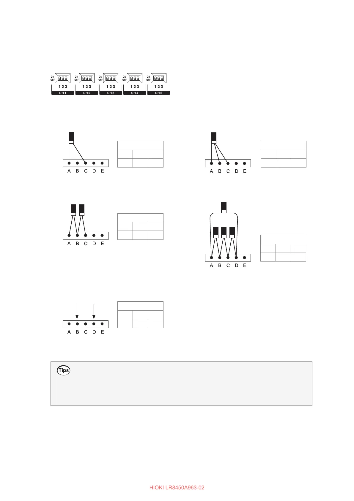
Setting the DIP switches for input connections
This section describes how to set the DIP switches for input connections.
The DIP switch is on in the upper position and o in the lower position.
DIP switches
(1) 1-gage method (2-wire setup)
DIP switch
OFF ON ON
1 2 3
(3) 2-gage method (adjacent sides)
DIP switch
ON ON OFF
1 2 3
(2) 1-gage method (3-wire setup)
(4) 4-gage method/converter
DIP switch
OFF ON OFF
1 2 3
DIP switch
ON OFF OFF
1 2 3
DIP switch
ON OFF OFF
1 2 3
When connecting a converter, the terminals function
as indicated below. If the converter output utilizes a
connector (such as NDIS connector), use a cable with
a connector on one end and loose wires on the other
to make the connection.
A Applied voltage (+)
B Converter output (−)
C Applied voltage (−)
D Converter output (+)
E Measurement GND
(5) Voltage input
Negative
input
Positive
input
Measuring strain
• After installing the strain gage and completing its wiring, perform auto-balancing before
measurement.
See “Measuring strain” in the Instruction Manual.
• Secure the strain gage wires in place and ensure that the gage itself is not subjected to force.
 Loading...


