32
SWMのリンケージ-2
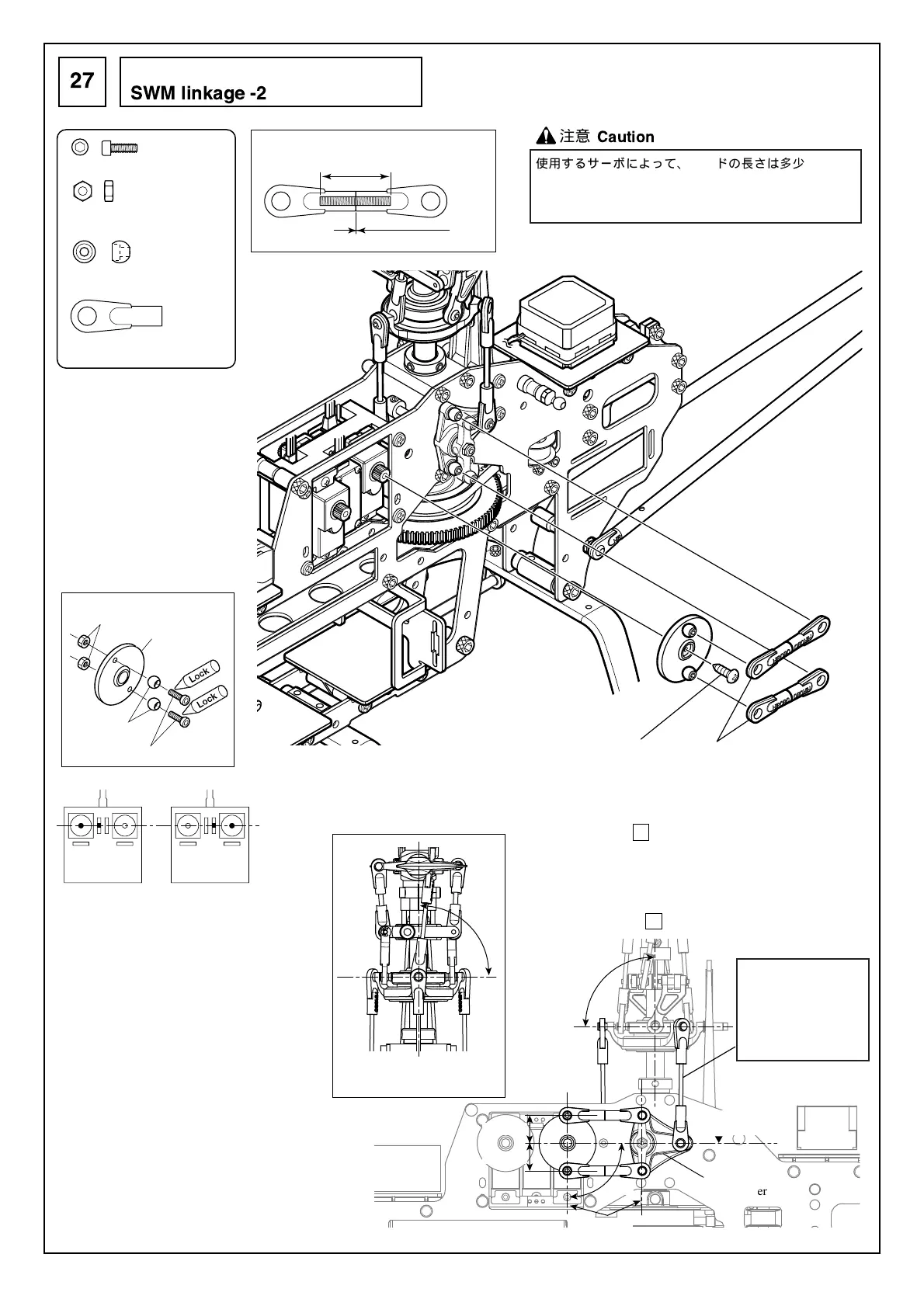
SWM linkage -2
27
注意
Caution
使用するサーボによって、ロッドの長さは多少変わりま
すので、サーボに合わせて微調整を行ってください。
Thelengthsoftherodsvarytosomedegreedepending
ontheservosused.Fine-tunethemaccordingly.
スワッシュプレート
が直角になるように
長さを調節する。
Adjustthelengthso
thattheswashplate
isperpendicular.
・SWMロッド③を取付調整後、機体を正面から見て、スワッ
シュプレートがマストに対して直角であることを確認して
ください。
・傾いている場合は 25 で取付けたSWM T型レバー/スワッシ
ュロッドの長さを調節し、直角にしてください。
・After having conducted installation adjustments on the SWM rod
③, looking at the unit from the front, make sure the swash plate
and the mast are perpendicular to each other.
・When inclined, adjust the length of the SWM T-type lever/swash
rod installed in section 25 and set it perpendicular.
モード I
Mode I
モード II
Mode II
ニュートラル
Neutral
送信機のスティックの 位 置
Position of the transmitter stick.
サーボホーン
Servo horn
M2ナット
M2 nut
EX ø5ボール
EX ø5 ball
M2X6CS
・送信機のエルロン、エレベーター、ス
ロットルの各スティック、およびトリ
ムがニュートラルの時、右図のように、
T型レバーが水平のときにサーボホーン
とT型レバーのボール位置が平行になる
ように、ロッドの調整をしてください。
・With the transmitter’s aileron, elevator, and
throttle sticks as well as the trim in neutral,
refer to the diagram in the right and adjust
the rod so that the servo horn and T-type
lever ball positions are aligned in parallel
when the T-type lever is horizontal.
約0mm
Approx. 0 mm
SWMロッド③ (2セット)
SWM rod ③ (2sets)
SWMロッド③
SWM rod ③
16mm
M2X6CS
.............................
2
M2ナット
...........................
2
M2 nut
EXø5ボール
.......................
2
EX ø5 ball
ロッドエンド
.....................
4
Rod end
90°
90°
90°
90°
T型レバー
T-type lever
正面から見た図
Front view illustration
平行
Parallel
水平
Horizontal
12.5 mm
12.5 mm
サーボに付属のネジ
Screw included with the servo