• EPS system control unit (ECU)
• Speed sensor
• Temperature sensor
• Battery voltage sensor
• Mechanical reduction transmission
mechanism(Reducer)
• Gear/rack type steering gear
• Steering rod joint
• Ball stud of steering knuckle
• Steering shaft and universal joint
■ Construction of EPS
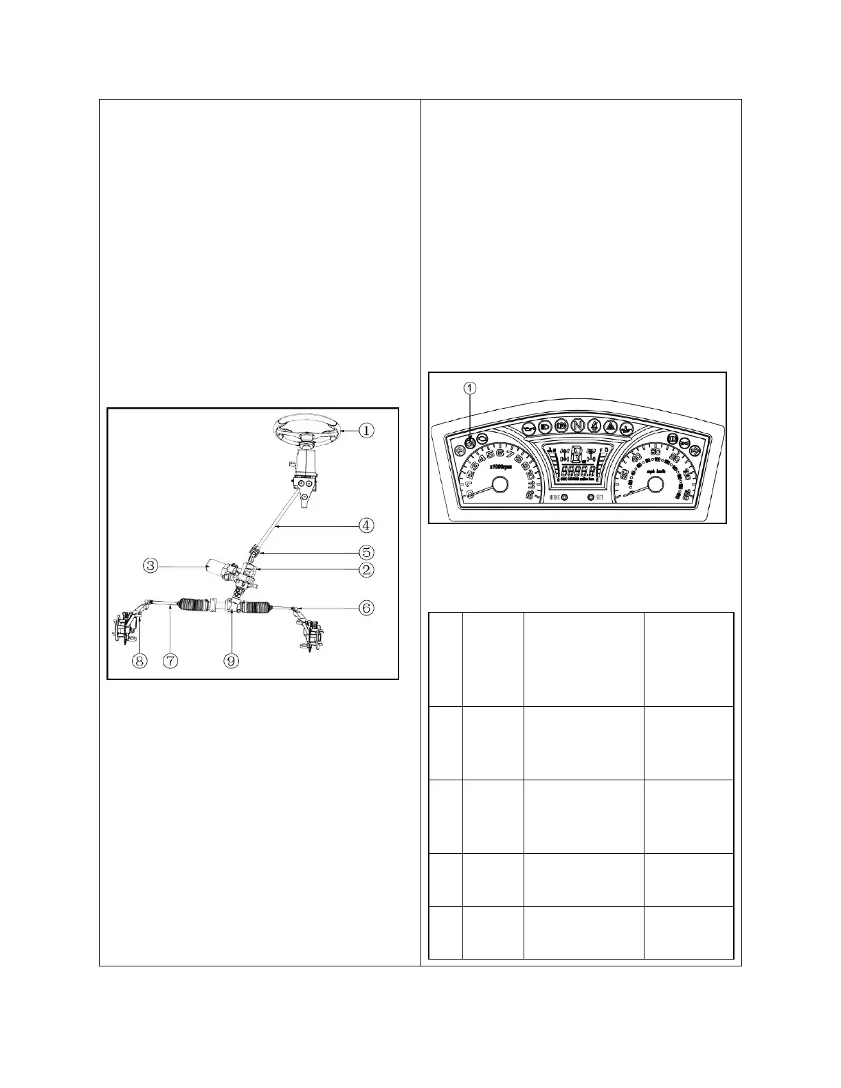
1. Structure chart of EPS
① Steering Wheel
② Reducer
③ Motor
④ Steering transmission shaft
⑤ Universal Joint
⑥ Tie Rod Joint
⑦ Tie Rod
⑧ Steering Knuckle
⑨ Steering Gear
The Meter is an important part of the
vehicle.
and monitors working condition of the EPS
system.
Faults can be displayed by a fault indicator
light and fault indicator of EPS system, so the
driver can acknowledge faults of the EPS in
time and take some measures to keep
himself/herself safe.
When a fault occurs on the EPS system, a
fault indicator light will be on. At the same
time, the fault indicator of EPS system will
display the fault code for maintenance.
① Fault indicator light of EPS system
Fault code diagram



 To Next Page