Hitachi recommends that the LCD touch console be available for secondary
maintenance application.
The LCD touch console is directly connected to the USB port #0 or 1 on front
panel module. The USB ports are standard USB connectors.
Figure 1-5 Connecting the LCD touch console
Hot-swappable Modules
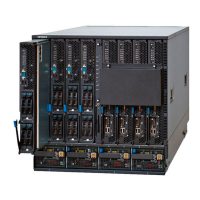
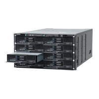
All modules are designed to be hot-swappable. The following figure shows the
side of the server chassis from which hot-swap is performed for each module.
Figure 1-6 Hot-swappable Modules
Power Distribution
One power cable is required per power supply module. (Four power cables
maximum) In the basic configuration, power cables from a server chassis
connect to a distribution box, and the distribution box is connected to the
power outlet. Hitachi recommends that power outlets use NEMA L6-30R (30
A/250 V) or IEC60309-32 (32A/240V) receptacles.
For more information, see;
– Hitachi Compute Blade 500 Series Site Planning Guide
System Overview
1-7
Hitachi Compute Blade 500 Series System Overview Guide
 Loading...


