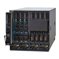
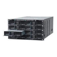
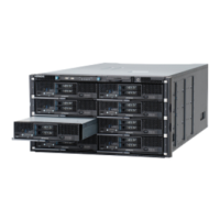
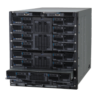
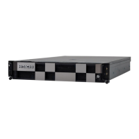
Figure 1-11 Label Tag
Switches, Indicators and Connectors
Figure 1-12 Front panel
Table 1-5 Front panel Switches, Indicators and Connectors
Location Name State Description
1 USB port 0 (USB0) - Server chassis USB ports.
2 USB port 1 (USB1) -
3 Forced power off
switch (POFF)
- Press and hold for at least four seconds to
force the main power off.
4 Power LED (PWR) Green-On Main power of one or more server blades
is on.
Green-Blink The server chassis is shut down by the
management module.
Amber-On Main power of all the server blades is off.
Amber-Blink Initialization when the power is first
supplied to the server chassis.
5 Alarm LED (ALM) Red -On Alarm, the server chassis found a non
redundant failure.
6 Warning LED (WRN) Amber-On Warning, a failure was detected in one or
more modules.
7 Identify LED (LID) Blue-On The server chassis is identified.
8 Buzzer stop switch
(BZSTP)
- Stops the buzzer
1-10
System Overview
Hitachi Compute Blade 500 Series System Overview Guide
 Loading...


