Location Name State Description
Green-Blink Random blink: In link communication
Slow blink: The FC port is online but
segmented.
Rapid blink: Diagnostic internal loop
back.
5 Uplink port status LED2 Amber-On Signal or communication received, but
not online.
Amber-Blink Slow blink: The port is disabled.
Rapid blink: The port has failed.
6 FC ports: 16 - 23 - External ports
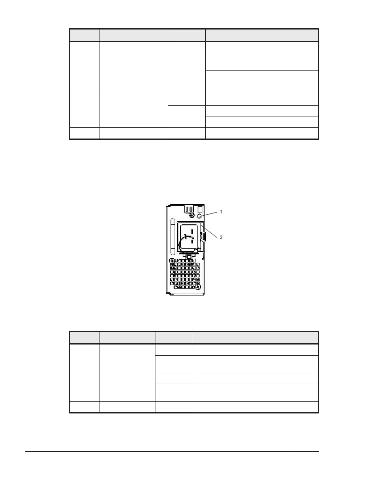
Power Supply Module
This section describes the power supply module.
Indicator and connector
Figure 1-42 Power Supply Module
Table 1-25 Power Supply Module Indicators
Location Name State Description
1 POWER LED (PWR) Green-On 12 V main power on.
Green-Blink 12 V main power off, but AC power is
present.
Amber-On Fail or system shutdown.
Amber-Blink No AC power to this power supply, but
others are supplied with AC power.
2 Inlet - IEC60320-C20 power inlet.
1-36
System Overview
Hitachi Compute Blade 500 Series System Overview Guide

 Loading...


