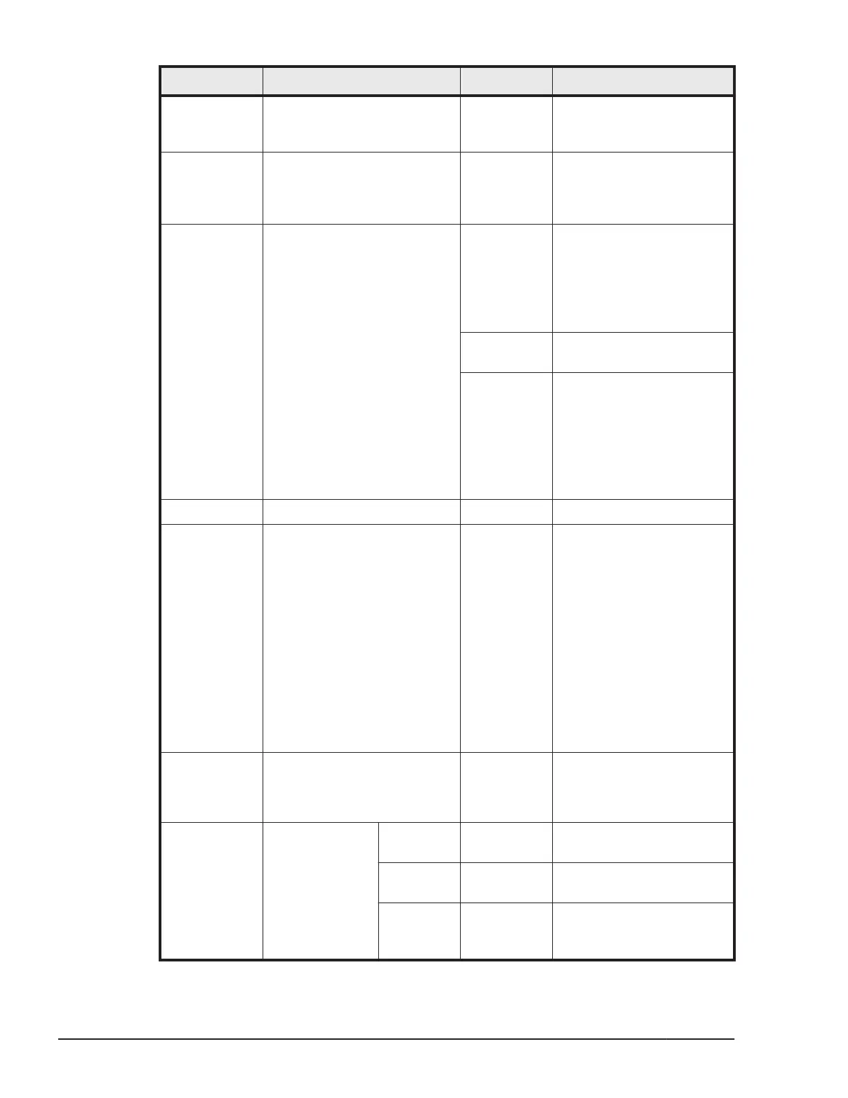
Location Name State Description
2 NMI reset switch - Press this switch to issue a
Non-Maskable Interrupt
(NMI) of the server blade.
3 KVM port - Provides VGA, serial port
and 2 USB port outputs.
Connect a KVM cable to
this port.
1
4 Power switch with Power LED - Press this switch to power-
on.
Press and hold this switch
for four seconds or more
to force the main power-
off.
2
Green-On Main power of the server
blade is turned on.
Green-Blink Main power of the server
blade is turned off.
Slow blink: The server
blade is ready to be turned
on.
Rapid blink: The server
blade is initializing.
5 Location Identify LED (LID) Blue-On Identifies the server blade.
6 Attention LED (ATN) Amber-On Configuration mismatch
errors other than failures
are detected in the server
blade, such as the installed
Mezzanine card does not
correspond to or does not
support the switch module.
Indicates explicitly that the
power button with LED was
pressed. The LED is turned
on when you press the
power button, and then
turned off when the main
power is turned on.
3
7 Alarm LED (ALM) Amber-On Indicates a fault that
requires an HDD to be
exchanged was detected in
the server blade.
8 Diagnostic Panel LP Green-On The LED panel on the
diagnostic panel is active.
S BRD Amber-On The motherboard needs to
be replaced.
MIS Amber-On Unsupported combination
of the DIMM, CPU, and
HDD.
1-14
System Overview
Hitachi Compute Blade 500 Series System Overview Guide

 Loading...


