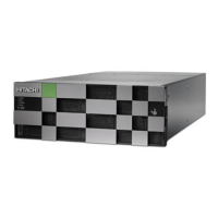
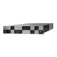
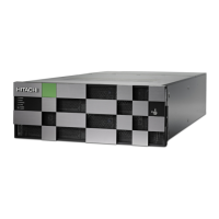
Item Name Color Description
3 ENC IN
connector
- Connects the drives to the ENC OUT port in the control chassis
either dir
ectly or via another drive bo
x with daisy chained
cables.
4
ENC OUT
connector
-
Connects the drives to the ENC IN port in the control chassis
either directly, or via another drive box with daisy chained
cables.
5 ENC OUT LED Green ON: Indicates that the port is connected to an IN port in the
controller. This can be performed directly or indirectly, as
previously described.
6 Console port - RJ-45 connector (not used)
7 Power Supply - Converts 200 VAC to the DC voltages used by the drives and the
ENC adapters.
8 RDY (Ready)
LED
Green OFF: No power is supplied to the system or the power supply
has failed.
ON: The power supply is operating normally.
9 AC IN LED Green ON: AC input is normal.
10 ALM (Alarm)
LED
Red Power supply has failed. Contact technical support. See Getting
Help in the preface of this manual.
11 AC Socket - For IEC60320-C14 plug: 200 - 240 VAC +8% - 6% 50/60 Hz
Figure 8 FMD drive tray
Drive chassis
Chapter 2: Storage system hardware overview
Hitachi Virtual Storage Platform G1000, G1500, and VSP F1500 Hardware Guide 50
 Loading...

