Chapter 6: Turning power on and off to the
storage systems
The following describes the prerequisites and procedures for turning the power on and
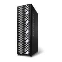
o to the VSP G1000, VSP G1500, and VSP F1500 storage systems during normal
oper
ating conditions or a po
wer failur
e.
Power control panel
The po
wer control panel is located in the top left corner of the controller. It is covered by
a 2U-high bezel that can be removed separately from the 8U bezel that covers the rest of
the controller.
The following illustration shows the switches and indicators on the control panel. The
following table lists the components and LED descriptions. All LEDs are shown ON to
demonstrate the LED color.
Figure 38 Storage system power control panel
Table 26 Storage system power controls and status indicators
Item Description
1 REMOTE MAINTENANCE switch
■
Set to ENABLE to allo
w remote maintenance.
■
Set to DISABLE to pre
vent remote maintenance.
2 ENABLE switch: Used to enable the PS ON/PS OFF switch. See
Power on procedures (on
page 122) .
Chapter 6: Turning power on and o to the storage systems
Hitachi Virtual Storage Platform G1000, G1500, and VSP F1500 Hardware Guide 119

 Loading...