142
7.1.2 Block Diagram
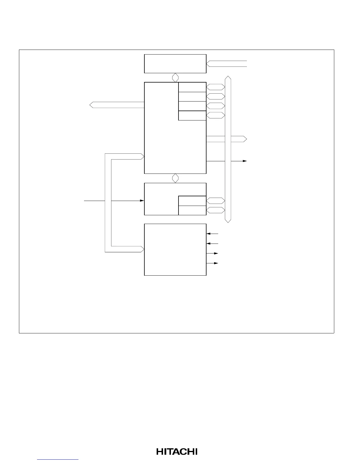
Figure 7-1 shows a block diagram of the bus controller.
Area decoder
Bus
controller
WAIT
ABWCR
ASTCR
BCRH
BCRL
Internal
address bus
External bus control signals
Legend:
ABWCR : Bus width control register
ASTCR : Access state control register
BCRH : Bus control register H
BCRL : Bus control register L
WCRH : Wait control register H
WCRL : Wait control register L
Internal control
signals
Wait
controller
WCRH
WCRL
Bus mode signal
Bus arbiter
CPU bus request signal
DTC bus request signal
CPU bus acknowledge signal
DTC bus acknowledge signal
Internal data bus
Figure 7-1 Block Diagram of Bus Controller
 Loading...