274
9.11.3 Pin Functions
In modes 4 to 6, each pin on port D automatically becomes one of the data bus I/O pins (D15 to
D8). In mode 7, each pin on port D functions as an I/O port and can be specified to function as an
input or output bit by bit.
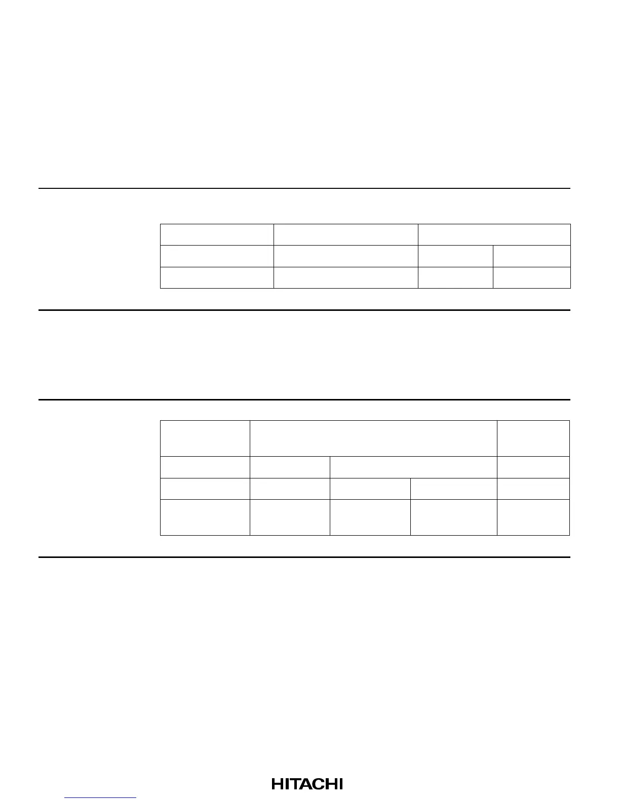
The function of pins on port D are as listed in tables 9-23 (1) and 9-23 (2).
Table 9-23 (1) Port D Pin Functions (H8S/2646, H8S/2646R, H8S/2645)
Pins Method of Selection and Pin Function
PD7/D15, PD6/D14,
PD5/D13, PD4/D12,
Pin functions are changed by a combination of the operating mode and the
PDDDR.
PD3/D11, PD2/D10,
Operating mode Mode 4 to 6 Mode 7
PD1/D9, PD0/D8
PDnDDR — 0 1
Pin function Data bus I/O (D15 to D8) PDn input PDn output
n = 7 to 0
Table 9-23 (2) Port D Pin Functions (H8S/2648, H8S/2648R, H8S/2647)
Pins Method of Selection and Pin Function
PD7/D15/SEG9 to
PD0/D8/SEG16
Setting of SGS3
to SGS0
Port SEG output
Operating mode Mode 4 to 6 Mode 7 —
PDDDR — 0 1 —
Pin function D15 to D8 I/O PD7 to PD0
input
PD7 to PD0
output
SEG9 to
SEG16
Note: Modes 4 and 5 are expanded modes with on-chip ROM disabled.
If segment output is selected, data input/output and interfacing to external ROM are no
longer possible. Therefore segment output settings should not be made in these modes.
 Loading...