Chapter 7 Explanation of Functions
7 - 73
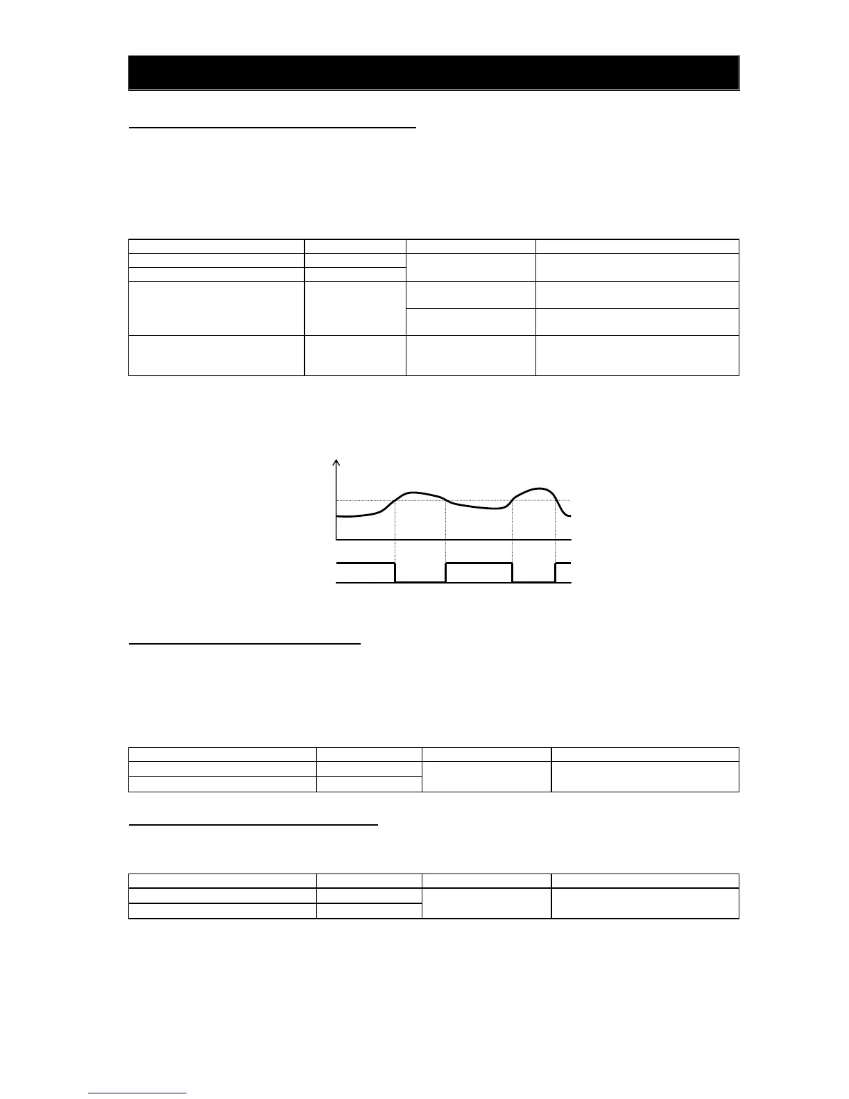
7.8.16 Low-current indication (LOC) signal
The inverter outputs the low-current indication (LOC) signal when the inverter output current falls to the
low-current indication signal detection level (C039) or less.
You can select one of the two signal output modes with the low-current indication signal output mode
selection (C038). In one mode, the LOC signal output is always enabled during the inverter operation. In
the other mode, the LOC signal output is enabled only while the inverter is driving the motor for
constant-speed operation.
Item Function code Data or range of data Description
Terminal function C021
43 LOC: Low-current indication signal
Alarm relay terminal function C026
Low-current indication signal
output mode selection
C038
00
Enabling the signal output during
operation
01
Enabling the signal output only
during constant-speed operation (*1
Low-current indication signal
detection level
C039
0.0 to "2.0 x rated
current" (A)
Setting of the threshold current level
at which to output the low-current
indication signal
(*1) When 01 (control circuit terminal) is selected as frequency source setting (A001), there is a case that
inverter does not recognize the speed as constant value due to sampling. In this case, adjusting is to be
made by setting C038=00 (valid during operation) or increasing analogue input filter (A016).
7.8.17 Inverter ready signal (IRDY)
The inverter outputs the inverter ready (IRDY) signal when it is ready for operation (i.e., when it can
receive an operation command).
- The inverter can recognize only the operation command that is input while the IRDY signal is output.
- If the IRDY signal is not output, check whether the input power supply voltage (connected to the R, S,
and T terminals) is within the range of specification.
Item Function code Data or range of data Description
Terminal function C021
50 IRDY: Inverter ready signal
Alarm relay terminal function C026
7.8.18 Forward rotation signal (FWR)
The inverter continues to output the forward rotation (FWR) signal while it is driving the motor for forward operation.
The FWR signal is turned off while the inverter is driving the motor for reverse operation or stopping the motor.
Item Function code Data or range of data Description
Terminal function C021
51 FWR: Forward rotation signal
Alarm relay terminal function C026
Output current (A)
Low-current indication
signal detection level
(C039)
Low-current
indication signal
ONON
 Loading...