Chapter 5 Wiring
5 - 12
5.6 Wiring of the control circuit
(1) Wiring instructions
1) Terminals L and CM2 are common to I/O signals and isolated from each other.
Do not connect these common terminals to each other or ground them.
Do not ground these terminals via any external devices. (Check that the external devices connected
to these terminals are not grounded.)
2) Use a shielded, twisted-pair cable (recommended gauge: 0.14-0.75 mm
2
) for connection to control
circuit terminals, and connect the cable insulation to the corresponding common terminal.
3) The length of cables connected to control circuit terminals must be 20m or less.
4) Separate the control circuit wiring from the main circuit wiring (power line) and relay control circuit
wiring. If these wirings intersect with each other unavoidably, square them with each other.
Otherwise, the inverter may malfunction.
5) When connecting a contact to a control circuit terminal (e.g., an intelligent input terminal), use a relay
contact (e.g., crossbar twin contact) in which even a very low current or voltage will not trigger any
contact fault.
6) When connecting a relay to an intelligent output terminal, also connect a surge-absorbing diode in
parallel with the relay.
7) Do not connect analog power supply terminals H and L or interface power supply terminals P24 and
L to each other. Otherwise, the inverter may fail.
8) Control circuit terminal block has two columns up and down. Lower terminal may wire difficult to
upper terminal wire to the first.
Therefore, please first wiring to lower terminal.
9) After wiring, gently pull the wire, please make lead wire have securely connected.
10) Make sure the wires are not shorted each other.
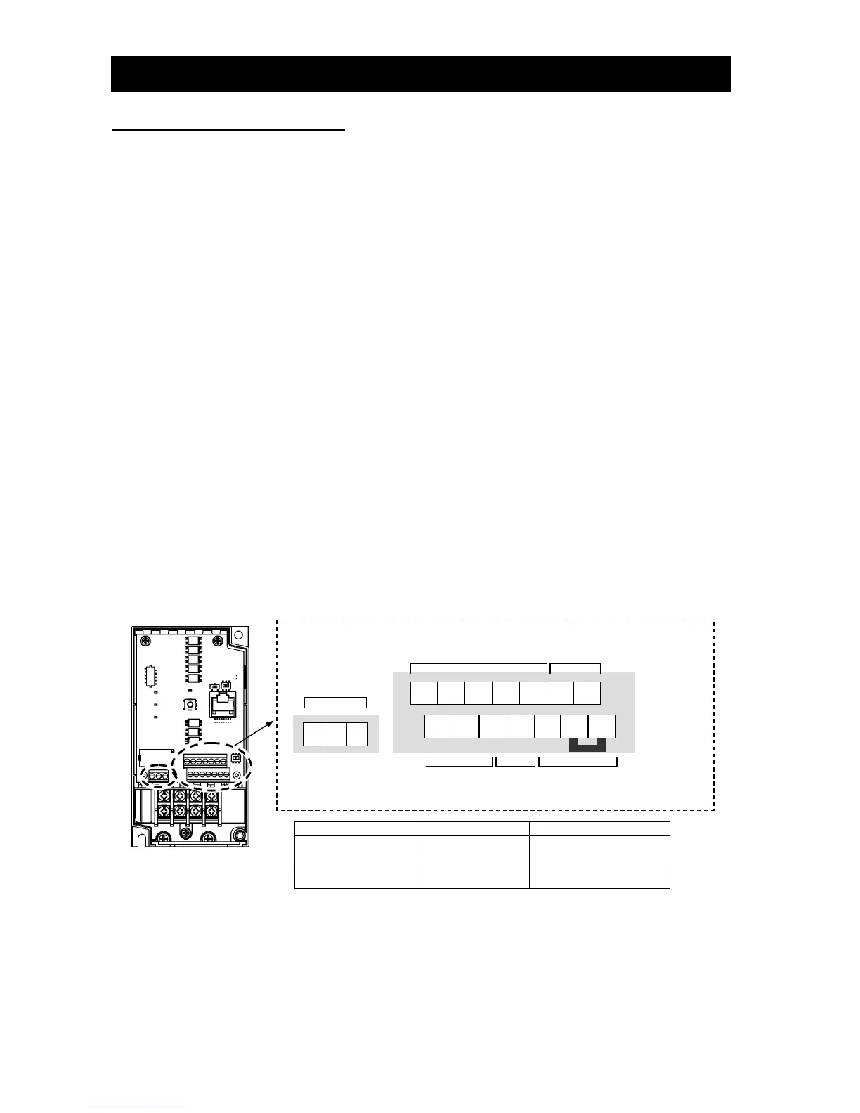
(2) Layout of control circuit terminals
terminal Screw diameter Tightening torque
Control circuit
terminal A,B
M2 0.2N・m
Relay terminal
M2
0.2N・m
Relay terminal
AL2 AL1 AL0
 Loading...