Inverter MODBUS RTU Driver
GP-Pro EX Device/PLC Connection Manual
23
5 Cable Diagrams
The following cable diagrams may be different from cable diagrams recommended by Hitachi IES Co., Ltd.
Please be assured there is no operational problem in applying the cable diagrams shown in this manual.
• The FG pin of the External Device body must be D-class grounded. Refer to your External Device manual for
more details.
• The SG and FG are connected inside the Display. When connecting the External Device to the SG, design
your system to avoid short-circuit loops.
• Connect an isolation unit if the communication is not stable due to noise or other factors.
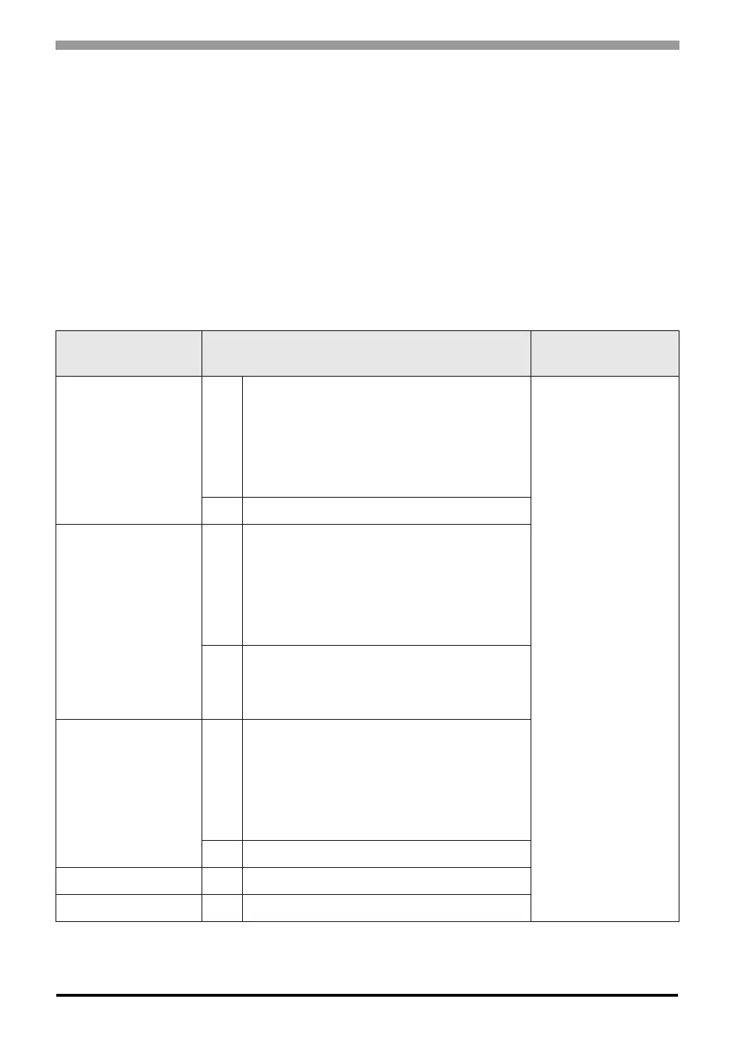
Cable Diagram 1
Display
(Connection Port)
Cable Notes
GP3000
*1
(COM1)
AGP-3302B (COM2)
ST
*2
(COM2)
LT (COM1)
*1 All GP3000 models except AGP-3302B
*2 All ST models except AST-3211A and AST-3302B
1A
COM port conversion adapter by Pro-face
CA3-ADPCOM-01
+
Terminal block conversion adapter by Pro-face
CA3-ADPTRM-01
+
User-created cable
Cable length: 250m or
less
1B User-created cable
GP3000
*3
(COM2)
*3 All GP3000 models except GP-3200 series and AGP-3302B
1C
Online adapter by Pro-face
CA4-ADPONL-01
+
Terminal block conversion adapter by Pro-face
CA3-ADPTRM-01
+
User-created cable
1D
Online adapter by Pro-face
CA4-ADPONL-01
+
User-created cable
IPC
*4
1E
COM port conversion adapter by Pro-face
CA3-ADPCOM-01
+
Terminal block conversion adapter by Pro-face
CA3-ADPTRM-01
+
User-created cable
1F User-created cable
GP-4106 (COM1) 1G User-created cable
GP-4107 (COM1) 1H User-created cable

 Loading...


