Inverter MODBUS RTU Driver
GP-Pro EX Device/PLC Connection Manual
3
1 System Configuration
The following table lists system configurations for connecting Hitachi IES Co., Ltd. External Devices and the
Display.
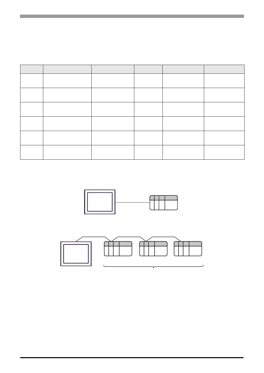
Connection Configuration
• 1:1 Connection
• 1:n Connection (when using either COM1 or COM2)
Series Inverter
*1
*1 is not added as an option. differs depending on the option.
Link I/F SIO Type Setting Example Cable Diagram
X200 X200-F
Serial port connector
on the inverter
RS-422/485
(2 wire)
"Setting Example 1"
(page 7)
" Cable Diagram 1"
(page 23)
SJ700 SJ700-
FF
RS485 port on the
inverter
RS-422/485
(2 wire)
"Setting Example 2"
(page 9)
" Cable Diagram 2"
(page 32)
SJ700-2 SJ700-
FF2
RS485 port on the
inverter
RS-422/485
(2 wire)
"Setting Example 3"
(page 11)
" Cable Diagram 2"
(page 32)
SJ200 SJ200-F
Serial port connector
on the inverter
RS-422/485
(2 wire)
"Setting Example 4"
(page 13)
" Cable Diagram 1"
(page 23)
L200 L200-F
Serial port connector
on the inverter
RS-422/485
(2 wire)
"Setting Example 5"
(page 15)
" Cable Diagram 1"
(page 23)
WJ200 WJ200-F
Control terminal
block on the inverter
RS-422/485
(2 wire)
"Setting Example 6"
(page 17)
" Cable Diagram 2"
(page 32)
Display
External Device
Display
External Device External Device External Device
Maximum number of External Devices: 16

 Loading...


