Inverter MODBUS RTU Driver
GP-Pro EX Device/PLC Connection Manual
39
2G)
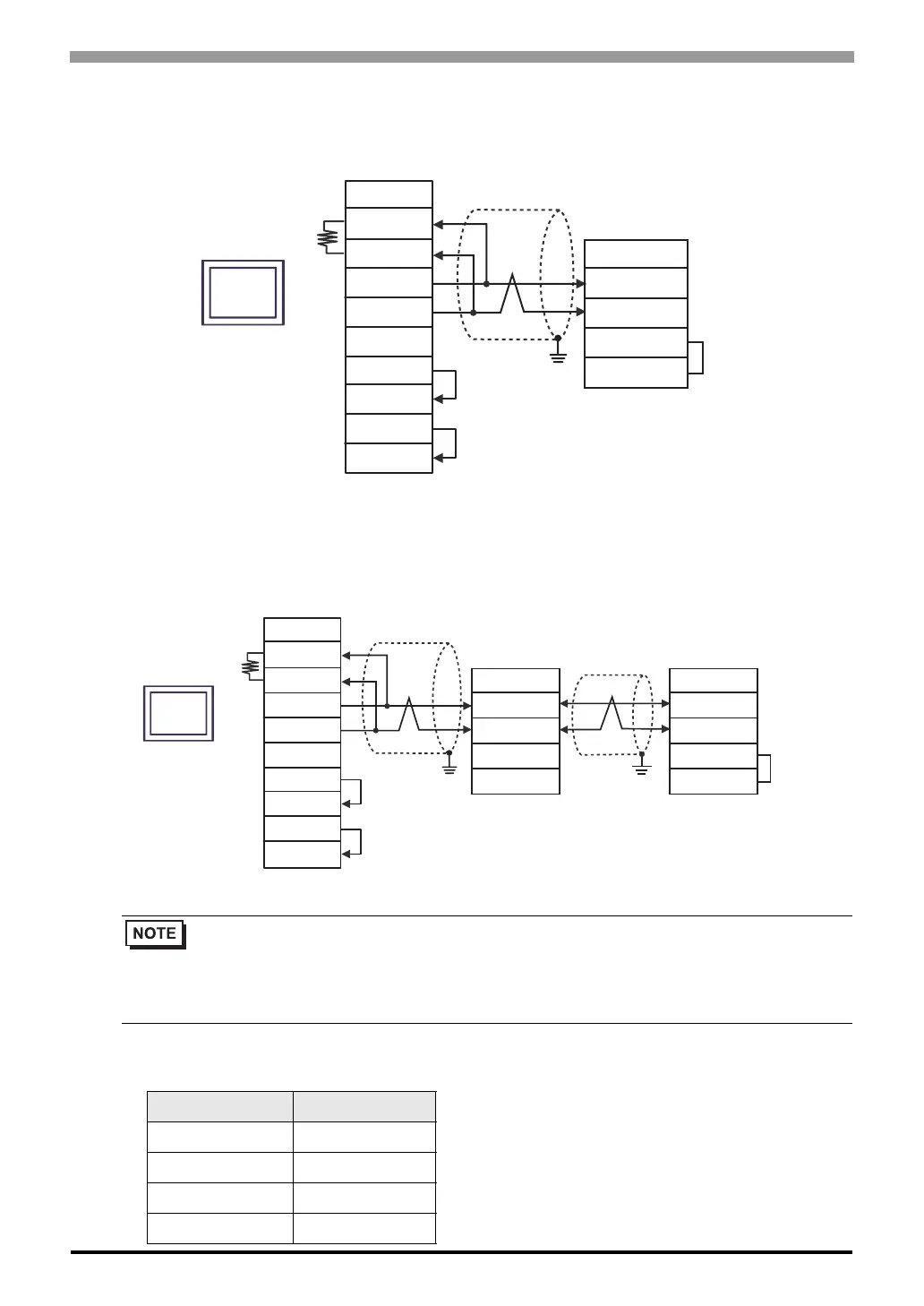
• 1:1 Connection
• 1:n Connection
*1 The resistance in the Display is used as the termination resistance. Set the value of the DIP Switch on the
rear of the Display as shown in the table below.
• Enable termination resistance by short-circuiting the terminatory External Device’s RP
terminal and the terminatory External Device’s SN terminal.
• To activate termination resistance on the WJ200 series, turn ON the inverter’s DIP Switch for
Terminal resistor.
DIP Switch No. Set Value
1OFF
2OFF
3OFF
4ON
Shield
Display
Signal name
RDA
RDB
SDA
SDB
SG
ERA
CSA
ERB
CSB
Termination
resistance*1
SP
SN
RP
SN
External Device side
TM2 Terminal Block
Signal name
Display side
Terminal block
Shield
Display
Signal name
RDA
RDB
SDA
SDB
SG
ERA
CSA
ERB
CSB
Termination
resistance*1
SP
SN
RP
SN
External Device side
TM2 Terminal Block
Signal name
SP
SN
RP
SN
External Device side
TM2 Terminal Block
Signal name
Shield
Display side
Terminal block

 Loading...


