Hardware Compatibility 12 (38)
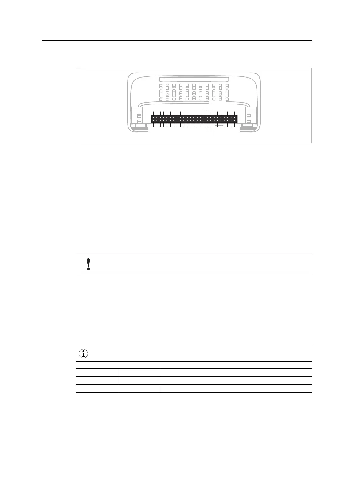
4.4 Host Application Interface
25
50
1
26
MD1
A1
A3
A5
A7
A9
A11
A13
D6
D4
D2
D0
VDD
VSS
OM1
CE
IRQ
RESET
GOP0
GIP0
LED2B
LED1B
Tx/OM3
MI1
VSS
VSS
A0
A2
A4
A6
A8
A10
A12
D7
D5
D3
D1
VDD
VSS
OM0
OM2
R/W
OE
GOP1
GIP1
LED2A
LED1A
Rx
MI0
MD0
Fig. 5
Some signals in the host application interface have modified functionality and/or functions which
must be checked for compatibility. See the following sections.
4.4.1 Tx/OM3
This pin is Tx only in the 30-series. It is tri-stated during power up, and driven by the Anybus
CompactCom UART after initialization. In the 40-series this pin is used as a fourth operating
mode setting pin (OM3). During startup after releasing the reset, this pin is read to determine
the operating mode to use. The pin is then changed to a Tx output.
In the 40-series, this pin has a built-in weak pull-up. If this pin, on a 30-series module or brick is
unconnected, pulled high, or connected to a high-Z digital input on the host processor, it will be
compatible with the 40-series. An external pull-up is recommended, but not required.
If this pin is pulled low by the host during startup, the 40-series module or brick will
not enter the expected operating mode.
Related Information: Anybus CompactCom M40 Hardware Design Guide (HMSI-216-126), Sec-
tion “Application Connector Pin Overview”
4.4.2 Module Identification (MI[0..1])
These pins are used by the host application (i.e your product) to identify what type of Anybus
CompactCom that is mounted. The identification differs between the 30-series and the 40-
series.
If your software use this identification you need to handle the new identification value.
MI1 MI0 Module Type
LOW LOW Active Anybus CompactCom 30
HIGH LOW Active Anybus CompactCom 40
MI[0..1] shall only be sampled by the application during the time period from power up to the
end of SETUP state. The pins are low at power up and before reset release.
Related Information: Anybus CompactCom M40 Hardware Design Guide (HMSI-216-126), Sec-
tion “Settings/Sync”.
Migrating from Anybus
®
CompactCom
™
30 to Anybus
®
CompactCom
™
40 Design Guide SCM-1202-043 1.1