OM 2012
CHAPTER 1. DESCR IPTION/OPERAT ION
SECTION 1. DESCRlPTlOlv
1.
Genera I
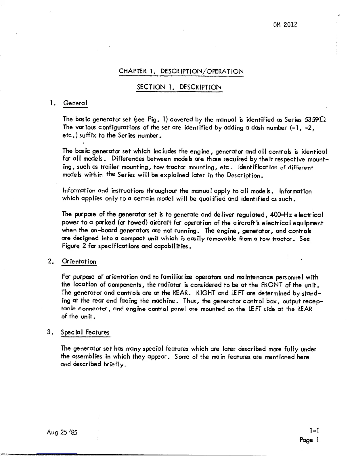
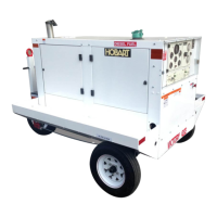
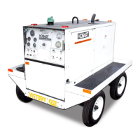
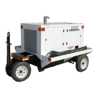
The basic generator set (see Fig. 1) covered by the manual is identified as Series 5355KD
The various configurations of the set are identified by adding a dash number (-1, -2,
etc.) suffix to the Series number.
The basic generator set which includes the engine, generatcr and ail controk is identical
for ail mode k. Differences between mode k are those required by their respective mount-
ing, such as trailer mounting, tow tractor mounting, etc.
Identification of different
mode k with in the Series wil I be explained later in the Description.
Information and instructions throughout the manual apply to ail mode k.
infcrmation
which applies only to a certain model will be qualified and identified as such.
The purpose of the generator set ‘a to generate and de liver regulated, 400-H~ e iectrica I
power to a parked (or towed) aircraft for operation of the aircraft’s electrical equipment
when the on-board generators are not running. The engine, generator, and ccntrok
are designed into a compact unit which is easily removable from a tow.tractor. See
Figure 2 fcr specifications and capabilities.
2. Orientation
.
For purpose of orientation and to familiarize operatars and maintenance personnel with
the location of components, the radiator k considered to be at the FRONT of the unit.
The generator and controk are at the REAR. RIGHT and LEFT are determined by stand-
ing at the rear end facing the machine. Thus, the generator control box, output recep-
tat ie connecta, and engine control pane I are mounted on the LE FT side at the REAR
of the unit.
3. Soeciai Features
The generator set has many special features which are later described mare fully under
the assemblies in which they appear. Some of the main features are mentioned here
and described briefly.
Aug 25,‘85
l-l
Page 1