OM 2012
l-3
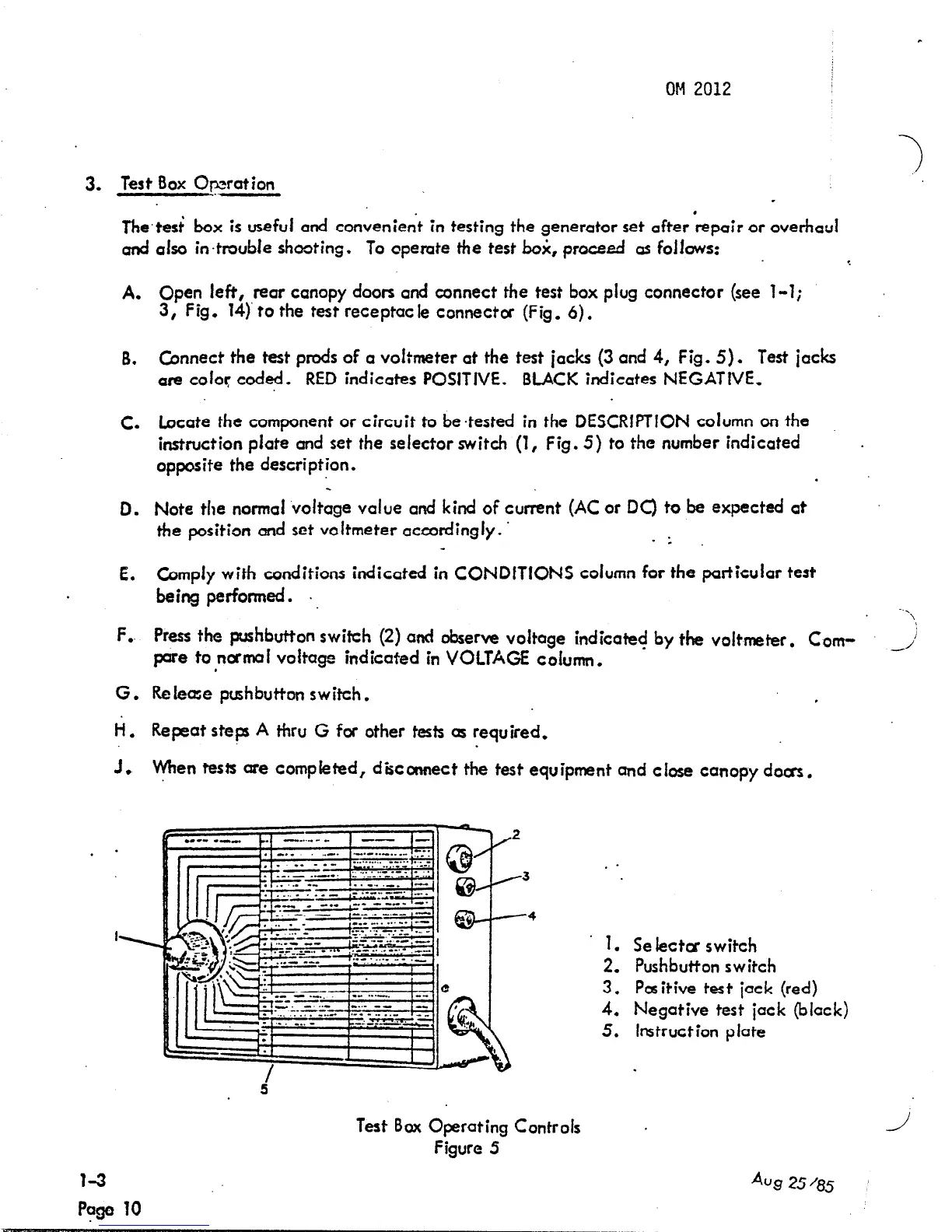
Test Box Opration
The,test‘ box is useful and convenient in testing the generator set after ‘repair or overhaul
and also in+roubte shooting.
To opemte the test bo& proceed as folfows:
A.
B.
c.
0.
E.
F..
G.
ii.
1.
Open left, rear canopy doors and connect the test box plug connector (see 1-l;
3, Fig. 14)’ to the test receptacle connector (Fig. 6).
Connect the test prods of a voltmeter at the test jacks (3 and 4, Fig. 5).
Test iacks
are coiol: cod*. RED indicates POSITIVE. BLACK indicates NEGATIVE,
Locate the component or circuit to be-tested in the DESCRlPTlON column on the
instruction plate and set the selector switch (1, Fig. 5) to the number indicated
.
opposite the description.
.
Note the normal voltage value and kind of current (AC or DC) to be expected at
the position and set voltmeter accordingly. ’
:
Campiy with conditions indicated in CONDITIONS column for the particular test
being performed. .,
\
Press the pushbutton swifch (2) and observe voltage indicate+ by the v&meter. Cow
par8 to rtcrm~f voitage indicated in VOLTAGE cofumn,
,j
Release pushbutton switch.
,
Repeat steps A thru G for other tests as required.
men tests are compieted, disconnect the test equipment and close canopy doas.
Page ‘10
Test Box Operating Controls
Figure 5
. .
1.
Se lectca switch
2,
Pushbutton switch
3.
Positive test jack (red)
4.
Negative test jack (black)
5. Instruction plate
J
Aug 25 ‘85