OM 2012
.
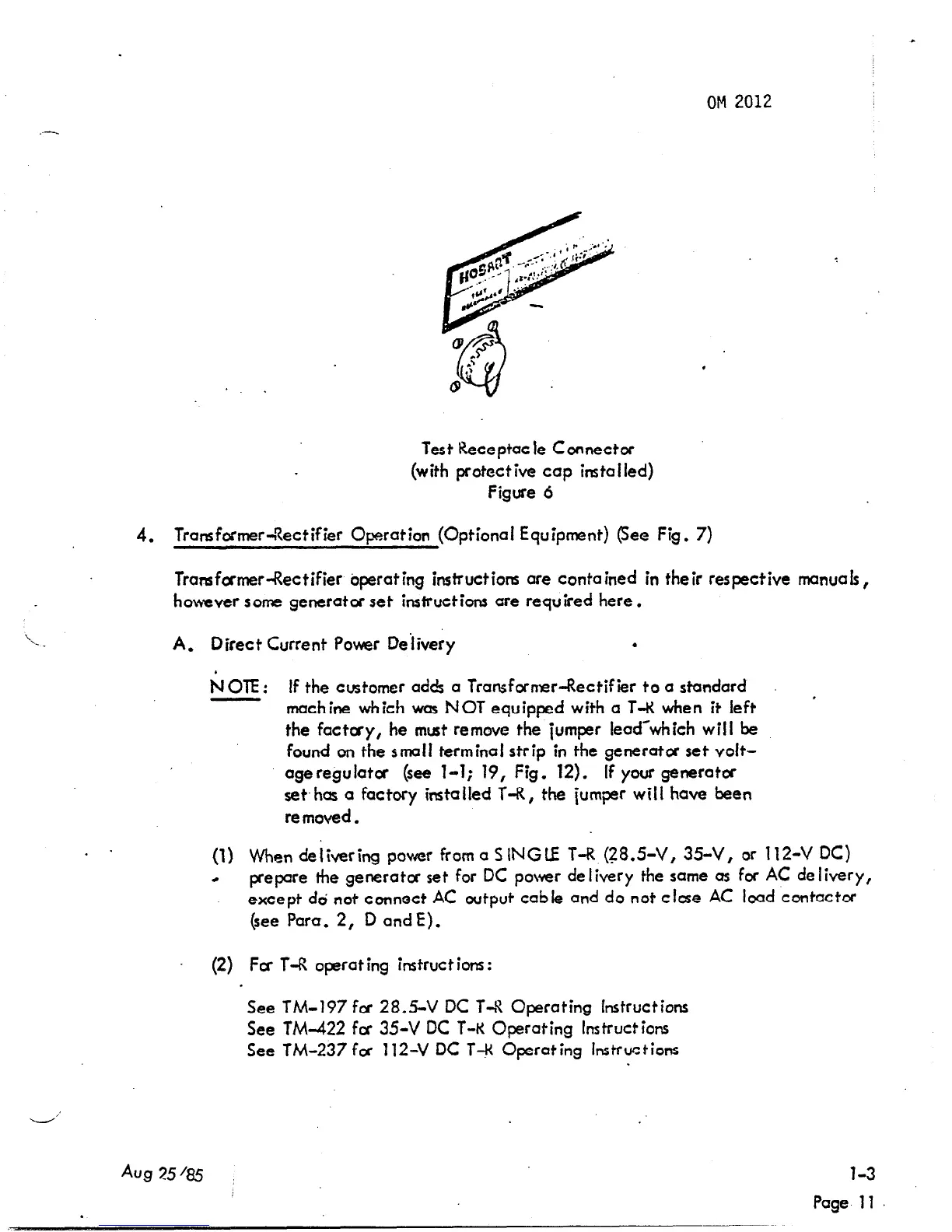
Test Receptacle Connectcc
(with protective cap installed)
Figure 6
4. TransformerT7ectifier Operation (Optional Equipment) (See Fig. 7)
Transformer-Rectifier operating instructions ore contained in their respective manual ,
hov.ever some generator set instructions are required here.
\
‘- .
A. Direct Current Power Delivery
.
NOIE: If the customer adds a Transfornsr-Rectifier to a standard
machine which was NOT equipped with a T-R when it left ’
the factcry, he must remove the jumper lead-which will be
found on the small terminal strip in the generator set voit-
age regulator (see l-l; 19, Fig. 12). if your generator
set.has a factory installed T-R, the jumper will have been
removed.
(1) When delivering paver from a SINGLE T-R.(?8.5-V, 35-V, or 112-V DC)
4
prepare the generator set for DC power de livery the same 0s for AC de livery,
except dd not connect AC output cable and do not close AC load contactor
(see Para. 2, D and E).
(2) Fa T-R operating instructions:
.
See TM-197 for 28.5-V DC T-!! Operating Instructions
See TM-422 for 35-V DC T-K Operating Instructions
See TM-237 fa 112-V DC T+ Operating Instructions
-’
Aug 25185
l-3
.
Page 11
 Loading...