OM. 2012
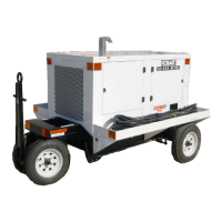
two Plcxisiass wirtdoe:; in the ICI-> rcclr dnc; which covers the control 1:~ and engine
C ontr 0 I p:lnD I .
Tilt lower vfi:>dcJ?*/ is slclnted outward at fr?e bsticm tc p<-svidz UCCCT,S
to engine co::tro!s v:h::n the doLtr is closed. A centruily-loeu
:cd tift+ eye nita::hc:d
to a IiR ing yoke exf-c,:ds througij the canopy top to provide a;, Giiachii:s point for clonic-:;,
cables, chr hook uSed ;o lift or:d move t!,lc gcncrcrto; set.
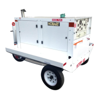
This assenlbiy is the basic generotor set without canopy and rol!-out tracks.
lt includes
all components required to generate and regulate 4QO Hz, 11.5/?00 V, three-p!lase p3’.*:cr,
and is operabie when provided with fuel and 12 V DC power. The engine-generator
assembly is mounted on a welded steel frame. A supcrstructurc, attached to the main
frame, provides mounting facilities 5x the canopy,
contrcl box, and eleciricc! equip-
ment and controls.
A. Basic Engine
The engine is a four-cylinder, in-line, diesel type (d-71 N), identified US Model
No. 004055C with “N” features, by the moncrfacturer, Detroit Diesel Engine Divi-
sion, General Motors Corporation, Detroit, Michigan. See Fig. 2 for general
specifications.
e
8.
Engine Manufacturer’s Equipment
-As received from the engine manufacturer, the engine includes the fo.ifoking equip-
.ment which is described in the Engine Operator’s Manual (Chapter 6).
(1) Twelve-volt electrical system includes starter and alternator with built-in
voltage regu later .
(2) Ether starting aid s&m
(3) Fuel strainer and fuel filter
(4) Full-flow oil filter
(5) Automatic shutdown system including temperature and pressure sensing
switches, a “hot-wire” relay, and a solenoid-operated, cam-and-latch
type shutdown valve in the blower air intake.
(6) Speed limiting governor
(7) Reverse-flow, engine-cooling fan to blow air outward through the radiator
Alf of the above equipment, except the fan,
is described in the Detroit Diesel
Operator’s Manual.
Aug 254~5
l-1
Page 9
 Loading...