Accenta/Optima Engineer’s Manual
8
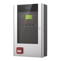
PA Circuit
It is recommended that no more than 10 Normally Closed type personal attack buttons may be wired in series
and then connected to the PA circuit.
Operational in Unset and Set, the PA circuit will cause a full alarm condition when activated. PA is
indicated on the control panel or RKP.
PA buttons may be fitted near the front door or in a bedroom.
Figure 9. PA Circuit
Panic
Button
Panic
Button
J2
PA
+
-
TAMP
+13V
0V
Board
1
2
3
4 5
6
7
8
Panel
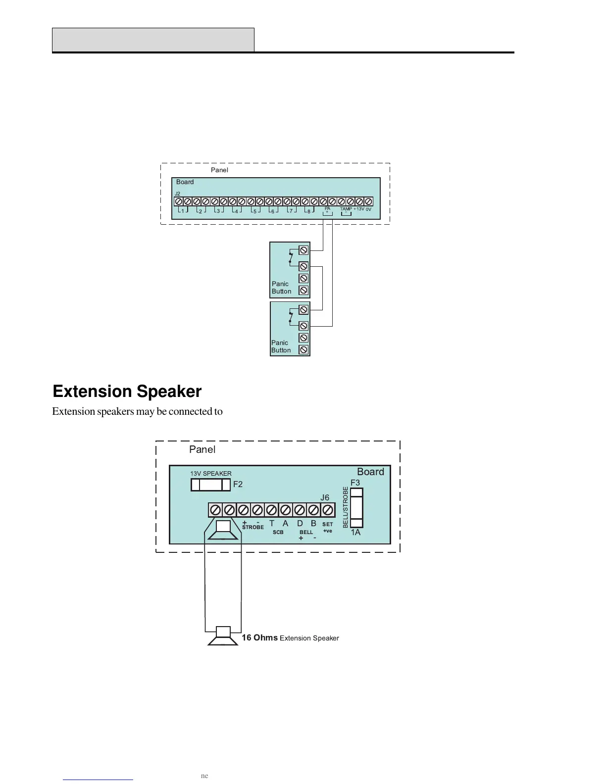
Extension Speaker
Extension speakers may be connected to the loudspeaker terminals to produce high volume alarm tones and
low volume entry / exit / fault tones.
Up to two 16 ohm extension speakers may be wired across the speaker terminals. Mounted in convenient
positions within the installation the extension speakers will reproduce all of the alarm tones generated by the
control panel.
A control marked VOLUME may be used to adjust the low volume entry/exit tones to suit environmental
conditions.
Figure 10. Extension Speaker Wiring
PA Circuit
! "
#
1A

 Loading...