Chapter 7. PARAMETER SETUP
7-8
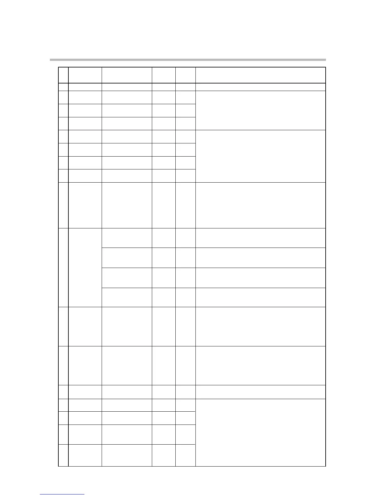
No. Item Code Item Factory User Setting
Setting Setting
12 G 5 .T 2.0
13 C P . 1 1 0U
14 C P . 1 2 200U
15
C P . 1 3 400U
16
C P . 1 4 600U
17 C P . 1 5 800U
18 C P . 1 6 1000U
19 C P . 1 7 1200U
20 F A S T 0
21 D 1 F F 5U
5.0
0.0
22 C Y . 1 10
23 C Y . 2 10
24 C Y . 3 –
25 D V -L 5U
26 D V -H 5U
27 H Y -L 5U
28 H Y -H 5U
0.1 to 60.0s
-1999 to 9999U
[Note]
When setup data C 1 1 setting is 0 (PID set auto-
switching OFF), “– – – –” is displayed and setting is not
possible.
-1999 to 9999U
[Note]
On heat/cool models, “– – – –” is displayed and setting
is not possible.
On other models, when setup data C 1 1 setting is 0
(PID set auto-switching OFF), “– – – –” is displayed
and setting is not possible.
0: 2X
1: 10X
2: 60X (10X)
3: 120X (10X)
[Note]
When setup data C 6 4 setting is 1 (program time
unit:min/s), the FAST factor is 10X for settings 2 and 3.
0 to 1000U
[Note]
This setting is displayed on 0D and 6D models.
0.5 to 25.0%
[Note]
This setting is displayed on 2G output models.
-100.0 to 50.0%
[Note]
This setting is displayed on heat/cool models.
[Note]
On 5G output models, “– – – –” is displayed and
setting is not possible.
5 to 120s (relay output)
1 to 60s (voltage output)
[Note]
On models whose output 1 is neither relay output nor
voltage output, “– – – –” is displayed and setting is not
possible.
5 to 120s (relay output)
1 to 60s (voltage output)
[Note]
On models whose output 2 is neither relay output nor
voltage output, “– – – –” is displayed and setting is not
possible.
[Note]
“– – – –” is displayed and setting is not possible.
0 to 1000U
[Note]
On models other than 3D output models, “– – – –” is
displayed and setting is not possible.
G.Soak time (CH1)
PID auto-switching
point 1-1
PID auto-switching
point 1-2
PID auto-switching
point 1-3
PID auto-switching
point 1-4
PID auto-switching
point 1-5
PID auto-switching
point 1-6
PID auto-switching
point 1-7
FAST factor
ON-OFF control
differential
Position-propor-
tional dead zone
Heat/cool control
dead zone
Output 1 time-
proportional output
cycle
Output 2 time-
proportional output
cycle
Unused
3-position control
deviation lower limit
3-position control
deviation upper limit
3-position control
lower limit hyster-
esis
3-position control
upper limit hyster-
esis

 Loading...


