E
3
Point Gas Monitor Technical Manual
Installation
6
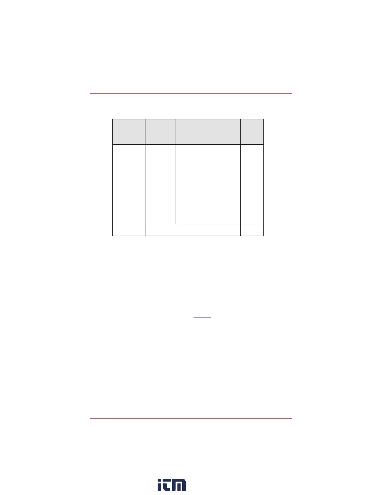
4. To mount the monitor, refer to the table for appropriate hardware and drill
size. Use the enclosed mounting template to drill into the vertical surface
if required.
Mounting
Surface
Example
Part
Description
Drill
Bit
Size
Drywall, Plaster,
Wood Paneling
QTY (2)
McMaster-Carr
#97121A013
Rounded head Toggle Bolt
· 6-32
· 3” long
· 1-1/2” wingspan toggle
· Pull Out Strength: 35 lbs
3/8”
Block, Brick,
Concrete
QTY (2)
McMaster-Carr
#97026A021
AND
QTY (2)
McMaster-Carr
#91555A111
Metal Anchor for Block and Brick
· 1” long
· Pull out Strength: 60 lbs
AND
Rounded Head Screw
·No. 6, 7 or 8 sheet metal or wood
screw
· 2” long
1/4”
Electrical Box or
Duct
As recommended by the manufacturer of the box or
duct
N/A
5. Tighten the mounting bolts or screws to 8.7 in-lb (1 Nm) maximum.
6. Remove the metal grounding plate before removing the knockouts.
7. Remove one of the knockouts (depending on where cables will enter the
housing) and affix appropriate conduit.
8. Run wiring through the conduit and the housing to the monitor, (See
wiring section).
9. Reinstall the PCBA.
10. Install the sensor cartridge.
11. Complete wiring as shown in the Wiring section.
12. Close the cover and tighten the cover screws to 29.7 in-lb (3 Nm).
13. Restore power to the monitor.
w ww . . co m
information@itm.com1.800.561.8187