Periphery components for ESSER FACP
82 TI 798960.GB0 / 04.20
12.4 esserbus
®
transponder 12 relays (Part No. 808610.10)
The esserbus
®
transponder works as a loop device on the loop, it is possible to expand the number of outputs
per ESSER FACP.
In ‘potential-free’ mode, no external switching voltage is required for relays K1 to K11.
In ‘monitored’ mode, the relays can be switched with an external power supply (UBext.). The monitoring of
UBext. enables a fault warning on the FACP if the permissible tolerance limits are not met. ‘Monitored’ mode is
configured using the service and programming software tools 8000.
The contact behaviour (NC / NO functionality) of relay contacts K1 to K11 can be individually programmed in the
customer data. The functionality as a common fault relay is permanently assigned to relay 12 (NO contact).
The maximum line length from the transponder to the external tool is up to 1000 m. There is also the option of
operating the transponder with the loop isolator (Part No. 788612).
• Only one loop address is needed per transponder
• Max. 100 transponders per FACP
• Max. 32 transponders per loop
• Max. 32 transponders per detector zone
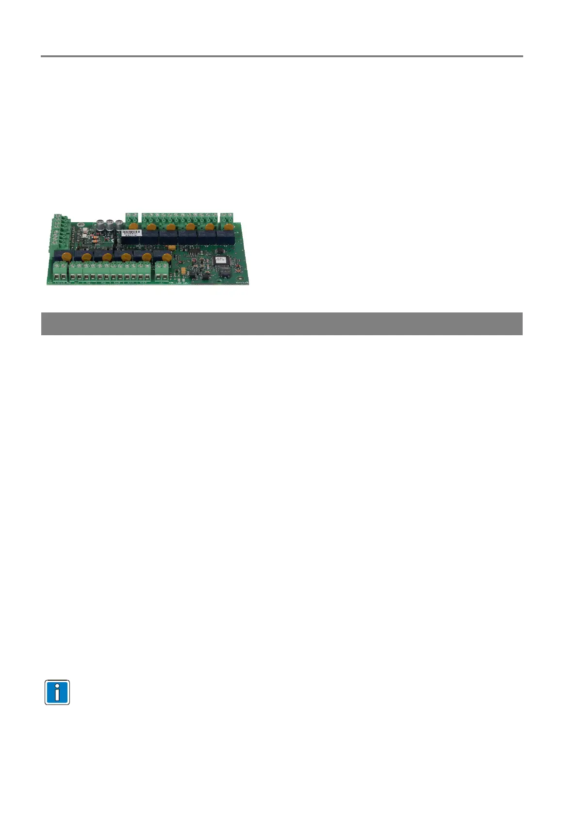
Fig. 50: esserbus
®
transponder 12 relays
Specifications
Loop
Rated voltage
Current consumption
Relays
Contact rating
(max. 3 A per transponder)
Contact type K1 to K11
Contact type K12
Common fault relay (NO contact)
Storage temperature
25 °C … +75 °C
Humidity
95% rel. humidity (no condensation)
Protection rating
Weight
Dimensions (w x h x d)
Specification
– 17:2005/-18:2005
VdS approval
Declaration of Performance
-20611130701
For further information and accessories refer to product catalogue and documentation of the devices.
 Loading...