56 107062-12 EN FR26 GLO 501 Printed in France
IMPROPER SYSTEM PERFORMANCE
Ensure independent stop circuit safety relays have mechanically linked contacts that prevent contact
overlapping in the event of a welded contact.
Failure to comply with these instructions could result in death or serious injury.
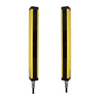
IMPROPER INSTALLATION OF FF-SB12E/R02 SERIES LIGHT CURTAIN
For FF-SB12R02 Series light curtains, use figure 3-8 wiring diagram ONLY.
Failure to comply with these instructions could result in death or serious injury.
Figure 3-8 Wiring Diagram of FF-SB12R02
The cycle-start push-button is the normal push-button used to start the machine cycle and not an additional
button for the operator.
* RC components: 220 Ω + 0,22 µF
**Emitter and receiver must be
grounded for proper operation. (see
figures 3-1 and 3-2)
Receiver
Emitter
and
Receiver
SUPPLY VOLTAGE
EARTH GROUND
SUPPLY VOLTAGE

 Loading...
