EasyManuals Logo

Honeywell FF-SB12 Series User Manual

Honeywell FF-SB12 Series
70 pages
To Next Page IconTo Next Page
To Previous Page IconTo Previous Page
Page #49 background imageLoading...
Page #49 background image
107062-12 EN FR26 GLO 501 Printed in France 55
IMPROPER SYSTEM PERFORMANCE
Ensure independent stop circuit safety relays have mechanically linked contacts that prevent contact
overlapping in the event of a welded contact.
Failure to comply with these instructions could result in death or serious injury.
IMPROPER INSTALLATION OF FF-SB SERIES LIGHT CURTAIN
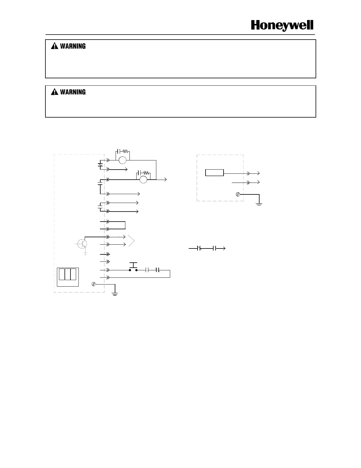
Use Figure 3-7 wiring diagram to ensure external relay monitoring of the FF-SB Series Light Curtain.
Failure to comply with these instructions could result in death or serious injury.
Figure 3-7 Wiring Diagram for FF-SB Series configuration (except FF-SB12R02)
NEUTRAL
EARTH
GROUND
(Emitter and Receiver
must be grounded
for proper operation)
POWER
C4
C5
B5
C3
C5
B4
B3
A
3
R1
Cycle Start
R2
Signal Beam
Status
B1
C2
C1
B2
FF-SB12, FF-SB14
FF-SB15
A
1
A
2
R2
A
dditional output
channel, may be
used to annunciate
to PLC
SUPPLY VOLTAGE
A
RC SUPPRESSOR
220 ohm + 0.22 µF
R1
SUPPLY VOLTAGE
EARTH
GROUND
(Emitter and Receiver
must be grounded
for proper operation)
MACHINE CONTROL
R1
R2
SCREW ON
A
5
INTERNAL FUSE
0,5 AMP
EMITTER AND
RECEIVER
A
4
NEUTRAL
SUPPLY VOLTAGE
Jumper Link position
on the Receiver
Power Board (to be
set up before
operation)
RECEIVER
Not
connected
*Two arc suppressors are provided with the light curtain.
*

Other manuals for Honeywell FF-SB12 Series

Questions and Answers:

Question and Answer IconNeed help?

Do you have a question about the Honeywell FF-SB12 Series and is the answer not in the manual?

Honeywell FF-SB12 Series Specifications

General IconGeneral
BrandHoneywell
ModelFF-SB12 Series
CategorySecurity Sensors
LanguageEnglish

Related product manuals