Galaxy Flex Installer Manual Wire detectors to zones
17
Wire detectors to zones
Note: Learning wireless detectors is covered on page 27.
Zones are the individual input circuits that are fully programmable using the Zones menu
(52 ent). This section describes how to change zone default settings, how to terminate
unused zones, and how to connect detectors.
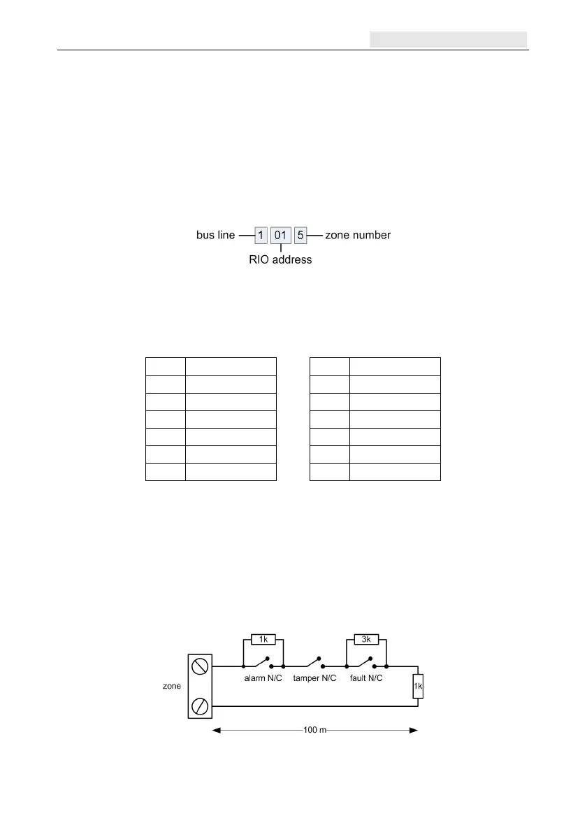
Zone addressing
The zone address format is:
The RIO address range is 00 to 12, and each RIO can support up to 8 zones. Camera zones
use these addresses in order of connection: 8001, 8011, 8021, 8031 and 8041.
Note: RIO 100 and 101 are the fixed on-board RIO addresses.
Address on-board zones as follows:
Zone Address Zone Address
1 1001 (Final) 7 1013 (Intruder)
2 1002 (Exit) 8 1014 (Intruder)
3 1003 (Intruder) 9 1015 (Intruder)
4 1004 (Intruder) 10 1016 (Intruder)
5 1011 (Intruder) 11 1017 (Intruder)
6 1012 (Intruder) 12 1018 (Intruder)
If required, use the Descriptor menu (52 ent 2 ent) to name your zones.
Zone configuration
Note: The circuit debounce time (the period the zone must remain in a state to register a
change in condition) is 300 ms.
The default zone configuration is 1 kΩ double-balanced with fault monitoring via a 3 kΩ
resistor (preset 11). In the following configuration a mask condition is generated if an alarm
and fault are signalled at the same time.

 Loading...


