Connect outputs Galaxy Flex Installer Manual
20
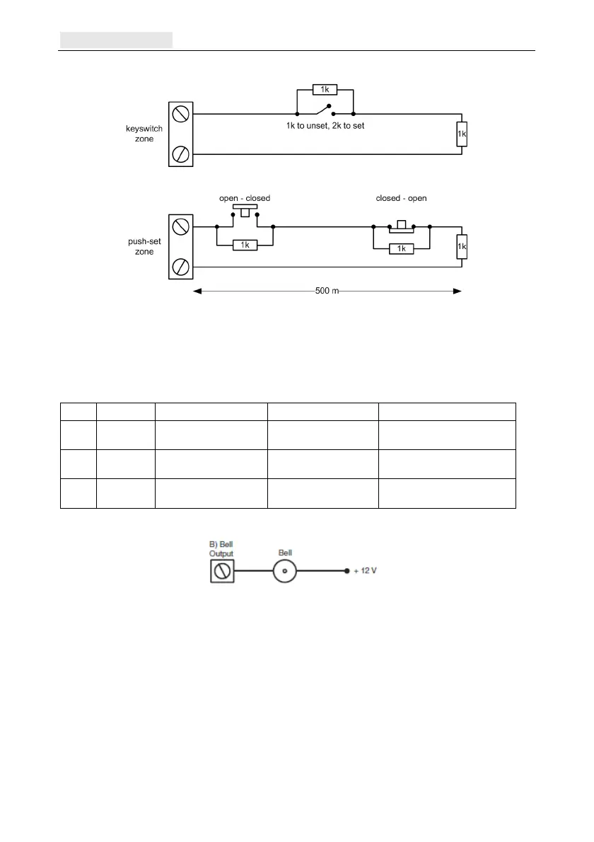
The wiring of the terminator and keyswitch zone type is shown in the following figure:
Figure 7 Terminator and keyswitch zone wiring
Connect outputs
Outputs are addressed in the same way as the zones. If using on-board outputs, connect and
a
ddress as follows:
O/P Address Function O/P type Connection
1 1001 Bells Open-collector,
switched negative
Connect load between OP1
and +12 V
2 1002 Strobe Open-collector,
switched negative
Connect load between OP2
and +12 V
3 99 Exit/Entry (E/E) horn AC audio to drive an
internal loudspeaker
Connect load (8–32 Ω)
between OP3 and +12 V
If required, use the Program Outputs menu (53 ent) to modify the default settings.
Figure 8 A typical application
Secure the tamper circuits
1. If
an external siren/bell/warning device is fitted, connect the tamper return line from the
device to the T terminal.
2. If an external siren/bell/warning device is not fitted, connect the T terminal directly to
the 0 V terminal.
3. If a relay output is required, fit the Output Option Board.
4. Replace and secure the panel cover.

 Loading...


