Galaxy Flex Installer Manual Appendix G: Peripherals
243
Installation instructions
The installation and wiring must be performed by a competent engineer. Connect the PSU to
the a.c. mains supply (230/240 Va.c. 50 Hz) via a 3 A fused connection outlet.
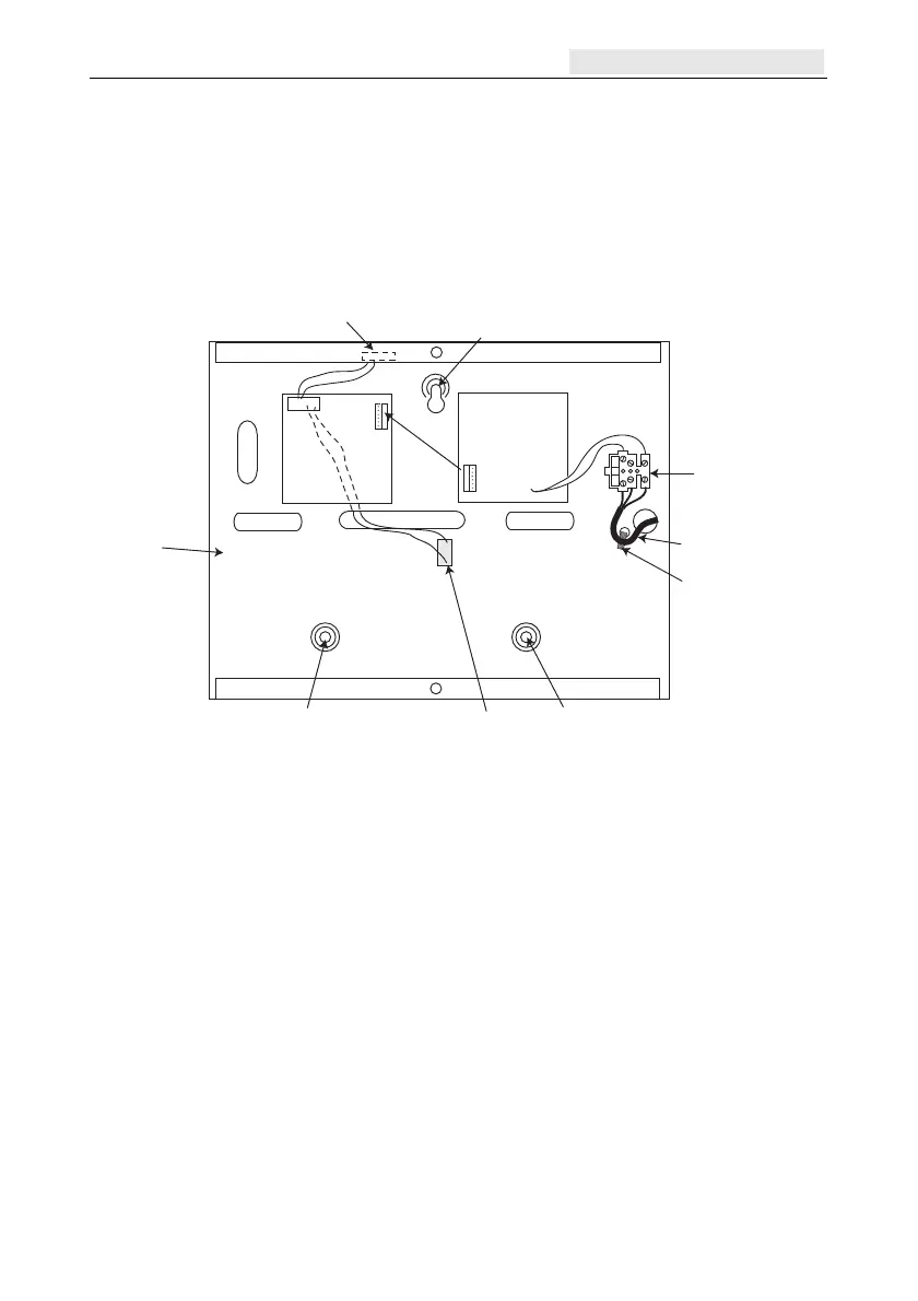
To install the panel:
1. Route the mains cable through the hole on the right-hand side of the enclosure base and
secure the panel base to the wall using three 40 mm No. 8 round-head steel screws.
Tie wrap
Mains cable
Terminal
block
Keyhole
slot (top)
Enclosure
base
Attaching hole
Attaching hole
Control
Unit
Power
Block
Off-Wall
T
amper
Micro-s
witch
Lid Tamper
Microswitch
6-way jumper lead
from power block
to control unit
2. Tie-wrap the mains cable as shown.
3. Using a three core cable that satisfies local regulations, wire mains power to the mains
terminal block as follows:
blue wire to the terminal marked N (Neutral)
green/yellow wire to the terminal marked E (Earth)
brown wire to the terminal marked L (Live)
Note: No other connections to the mains terminal block are permitted.
All wiring must be in accordance with local regulations and the installation must
conform to EN60950.
4. Apply mains power. This unit can be powered up from the battery by momentarily
shorting LK10. Never leave LK10 connected as deep discharge of the battery will
occur. LK10 is for start-up only.

 Loading...


