Fire Alarm Control Panel IQ8Control C/M
FB 798951.GB0 / 01.09 35
BR2 Solder jumper to set whether the two batteries are connected and the monitoring for the free
battery connection should be switched off.
Open (default)
Î Connection of two batteries >Battery 1+2<
closed
Î Connection of a single battery only to connector >Battery 1<.
(The power charge and monitoring of >Battery 2< is disabled)
BR 3 / BR 4
Solder/jumper for wiring the LCD indicator panel via the RS 485 interface
BR7
Solder jumper for enabling an internal printer
D21
Integrated circuit, replacement not required
F1
Mains fuse T1.25A H / 230 V DC
F2
Fuse T2,5A Î battery charge current, battery 1
F3
Fuse T2,5A Î battery charge current, battery 2
F4
Fuse T2A Î 12 V DC supply voltage +Ub
ext
for external devices
V46
lights during emergency operation Î Limited functionality of the Panel
S2
DIL switch Î Operating mode "OFF" (factory default)
Î Service mode ”ON“ (software update via USB interface)
V62 / V63 LED V62 lits red Î Reversed polarity of the connected TTY cable
LED V63 lits green
Î to check data communication if the TTY-interface is enabled
X1
Transformer connection (primary site)
X2
AC mains connector terminal L1/U, N, PE; for cable with 1,5 - 2,5 mm
2
(#12-14 AWG)
X3 Connector for the micro module slot, the internal serial interface TTY / RS 485-1, the common
trouble relay, inputs
I1 and I2, the control voltage for the built-in printer and the supply voltage
(12 V DC, Ub
ext
) for external equipment
The RS 485-2 interface connection is not supplied!
X7/X8 (LED V2)
Cover contact connection (FACP housing). LED V2 lights while the cover is open.
X9-A, 10-B
Connector for the power supply module (Part No. 802426 from Index G)
X11-A, 12-B
Micro module slot for a selectable micro module
X23 Connector for the built-in printer via a 26 pole ribbon cable
(For 19” racks the ribbon cable Part No. 750756 max. 50 cm or 750757 max. 120 cm is required)
X24
Connector for the operation panel via a 40 pole ribbon cable
X27, 28, 29, 30 Jumpers to configure the EMI protection for the terminals if an essernet
®
micro module is
connected.
X31
Connector for the Service-PC (optional panel interface required)
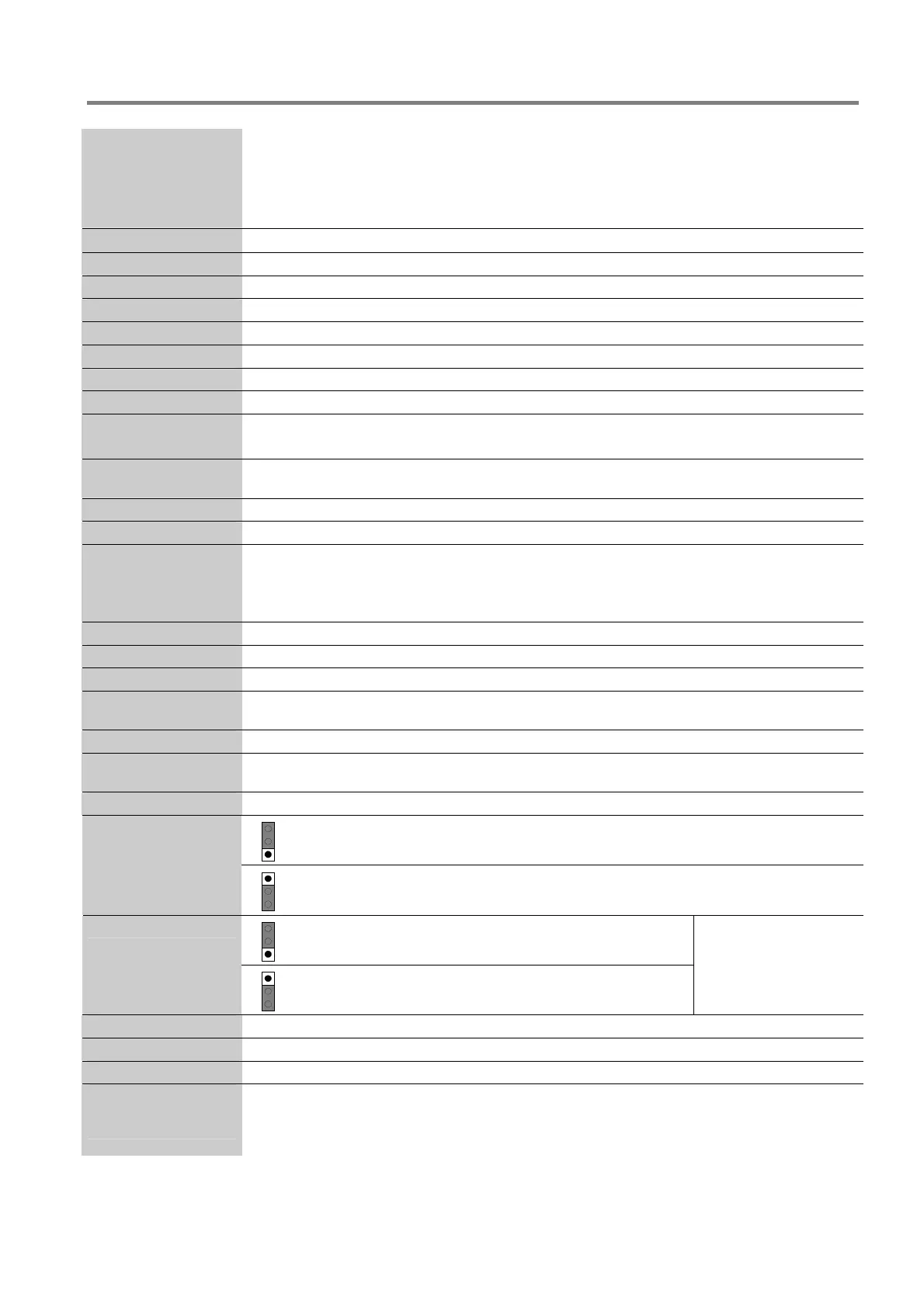
1
2
3
Pos 1/2
Î RS485-1 terminating resistance activated
X32
1
2
3
Pos 2/3
Î RS485-1 terminating resistance not activated
1
2
3
Pos 1/2
Î RS485-2 End of line resistor activated
(do not alter factory default)
X34
1
2
3
Pos 2/3
Î RS485-2 terminating resistance not activated
The RS485-2 interface is
not supplied for this panel
version.
X33/35
Jumper for the RS 485-2 interface (do not alter position)
X45, X46
Jumper for factory settings only ( do not alter ISB)
USB
Connector for the service-PC and USB-Interface for a System software update.
Ethernet, Phone box,
HW FAILSAFE, USL,
ISB, Smart card
Internal devices and terminals for future system developments

 Loading...


