Fire Alarm Control Panel IQ8Control C/M
36 FB 798951.GB0 / 01.09
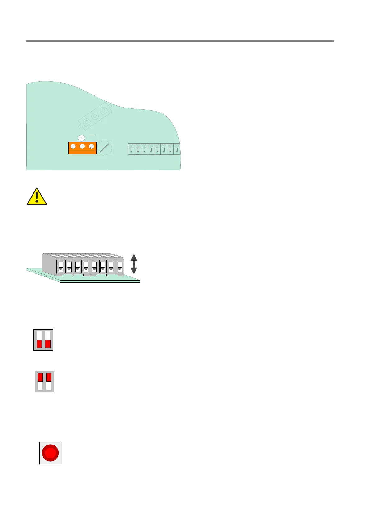
Connection of the AC mains voltage and batteries
The AC mains voltage must be connected to this terminals of the Basic module. Refer to section “power supply
module” for detailed information.
N
L1
U
X2
Mains
230V~
Fig. 29: Connection of the AC mains voltage and batteries
Danger - Electrical shock !
Disconnect all power from the panel before carrying out any installation work! Observe before
connecting the AC mains voltage (230 V AC) the specifications given on the panels nameplate
(adhesive label) inside the housing.
Connection terminals
Connector: removable, max. 1.5mm
2
removable
Fig. 30: Connection terminals removable
DIL Switch S2
S2
OFF
Normal operation
Î Position "OFF" (factory setting)
S2
ON
Service mode
Î Position "ON“
The LED V50 lits for an optical indication
The service mode will be activated after a panel reset and displayed at
the operation panel.
Reset Button
S1
Reset
Press the RESET button to restart the panel. Alarm and fault messages are reset, all
detector zones and primary loops are switched on and all changed switch settings are
read in.
A panel cold start using the RESET button is only possible when the housing contact
(panel housing) is open. If the panel interface was connected to the USB input, the
connection is detected only after a reset.

 Loading...


