10 MS-5UD/MS-10UD Series PN 52626:B 8/01/2008
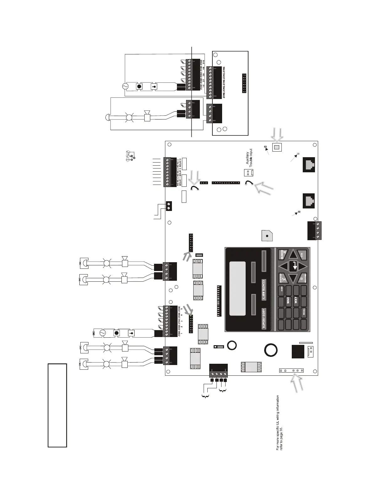
MS-5UD Series Main Circuit Board
DACT Phone Line Jacks
(Nonpower-Limited)
Resettable Power - 24 VDC filtered,
power-limited (0.500 amps maximum)
to smoke detectors (IDC).
Supervision required.
Nonresettable or Resettable Power
Jumper selectable by JP31, 24 VDC filtered,
power-limited (0.500 amps maximum)
Supervision required. NonresettablePower
suitable for powering annunciators, Resettable
Power suitable for powering smoke detectors.
Configure TB9, Terminals 1 & 2
as Resettable or Nonresettable Power.
• Resettable Power - jumper JP31
pins 2 & 3.
• Nonresettable Power - jumper JP31 pins 1 & 2
(as shown).
Special Application Power
NAC #1, #2, #3 & #4, Style Y (Class B) (Supervised, Power Limited)
(See Style Z illustrated near right edge of board).
4.7K , ½ watt
End-of-Line Resistor
PN 71252
Nonsupervised relay contacts
Contact Ratings:
2.0 amps @ 30 VDC (resistive)
0.5 amps @ 30 VAC (resistive)
Contacts shown below in normal
condition (AC power with no alarm,
trouble or supervisory activity).
A Fail Safe Trouble
relay switches to the
NC position during
trouble conditions and
under loss of all power.
Special Application
DC Power Outputs (24 VDC)
Nonsupervised, power-limited circuits
Supervise with a power supervision relay EOLR-1
Battery (see note 3)
Basic System Connections
5-Zone Panel
Notification Appliance Circuits (see note 1)
3 Programmable Relays
Alarm*
Trouble*
Supervisory*
NO NC C
24 VDC, supervised,
nonpower-limited
NO NC CNO NC C NO NC C
(* )Factory default relay programming
Power Supply Connector J15
NAC #1
+
+
+
4
3
FIRE ALARM
AC POWER
TROUBLE
1
4
7
*
2
3
1
5
6
89
0
#
ABC
DEF
GHI
JKL
PRS TUV
QZ_
_/.
CLEAR
ESC
MODE
ST
ENTER
ALARM
DRILL
RESET
J12
BATTERY
- +
TB5
TB4
TB8
TB9
J2
J15
J3
JP24
JP31
JP30
J5
J4
J6
J8
J9
TB3
GND PWR
ANN-BUS
A B
RST AUX
PWR
RST/NONRST
AUXPWR
OUT1 OUT2
4XTM OPT BD
Cut this jumper to supervise
the 4XTMF module when
installed (see J4 & J5)
Cut this jumper to
enable Supervisory
relay when 4XTM
module is installed
2
1
JP43
Class A Converter Module
-
+
+
-
3
2
1
NAC #2
+
+
+
B
+
B
-
11
B
+
B
-
22
B
+
B
-
11
Initiating Device Circuits
IDCs 1 through 5, Style B
(Class B) (Supervised,
Power Limited)
(See Style D illustrated
near right edge of board).
4.7K , ½ watt
End-of-Line Resistor
PN 71252
Remove jumper JP43
to disable Ground Fault
Detection circuit (only
with approval of AHJ).
+
+
+
TB5/
TB7
TB4/
TB6
OUT1/3 OUT2/4
B
+
B
-
11 2
B
+
B
-
11
OUT OUT
TB2
TB1
J2
Class A Converter Module
Dummy load all unused circuits with
4.7K , ½ watt End-of-Line resistors
Style Z (Class A) NAC
Style D (Class A) IDC
+ - + -
+ - + - + - + - + -
Important!
Removing Ground Fault
DisableJumper JP43 voids UL/NFPA
Style/Class identifications for circuits.
Remove jumper JP43 only with the
approval of the AHJ
(Authority Having Jurisdiction).
- +
TB2
Remote
Synchronization
Output (see note 2)
Special Application Power
24 VDC filtered, supervised
and power-limited.
0.040 amps maximum.
Requires ELR.4.7K
Primary Phone
Active LED
Secondary Phone
Active LED
Primary
Secondary
Kiss-off LED
- +
NAC #3
+
+
+
TB7
OUT3 OUT4
NAC #4
+
+
+
B
+
B
-
11
B
+
B
-
22
+ - + -
J7
J11
USB Port for local programming using
a personal computer and PK-5X Utility
Notes:
1. MS-5UD-3(E) = 2.5 amps max. per NAC
MS-5UD-7(C/E)= 3 amps max. per NAC
2. Remote Sync Output is required only for
the MS-5UD-3(E): refer to “Remote
Synchronization Output” on page 31
3. 18 Amp Hour max. for MS-5UD-3(E)
26 Amp Hour max. for MS-5UD-7(C/E)

 Loading...