Installation
MS-5UD/MS-10UD Series PN 52626:B 8/01/2008 49
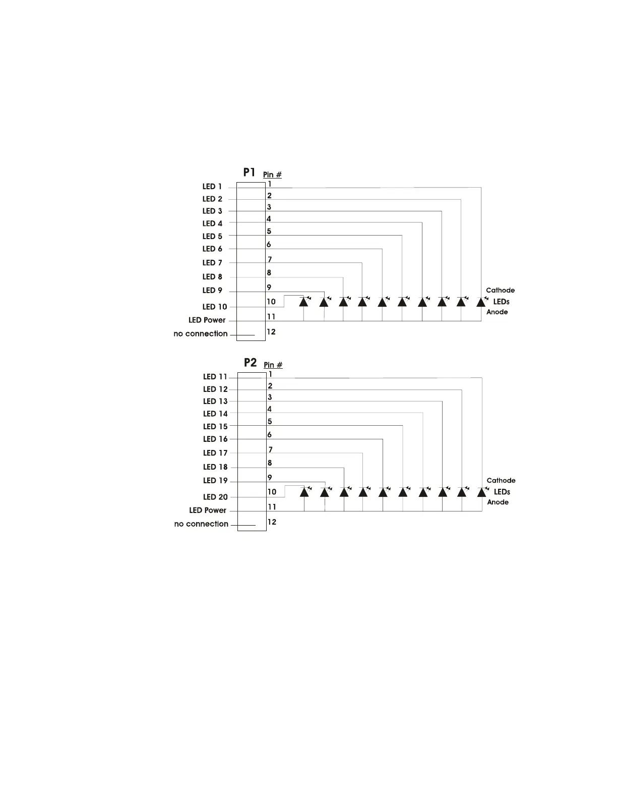
2.8.7.4 ANN-I/O Module LED Wiring
There are four 12-pin connectors on the ANN-I/O module for connecting LEDs. Each set of 10
LEDs get their power from Pin 11 of the corresponding connector. Internal resistors are sized
so that there is approximately 10 mA of current for each LED. No series resistors are required.
LED outputs are mapped to output circuits. Refer to the section titled "ANN-I/O LED Zone
Assignments" on page 83 of this manual.
The LEDs are wired as illustrated in Figure 2.24. Note that the illustration depicts only
connectors P1 and P2. Wiring is identical for P3 (LEDs 21-30) and P4 (LEDs 31-40).
Figure 2.24 ANN-I/O Board Layout
 Loading...