Power Supply Calculations
MS-5UD/MS-10UD Series PN 52626:B 8/01/2008 135
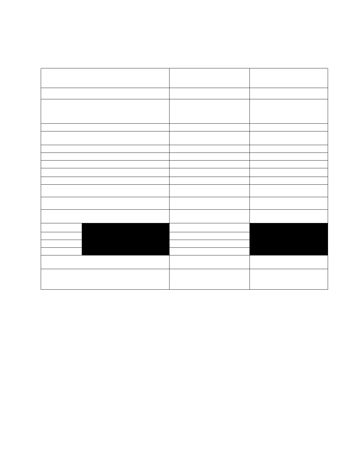
Table 7-3 contains three columns for calculating current draws. For each column, calculate the
current and enter the total (in amperes) in the bottom row. When finished, copy the totals from Cal-
culation Column 2 and Calculation Column 3 to Table 7-4 on page 136.
TABLE 7-3:System Current Draw Calculations
Device Type
Calculation Column 1
Primary, Non-Fire Alarm Current
(amps)
Calculation Column 2
Secondary, Fire Alarm Current
(amps)
Calculation Column 3
Secondary, Non-Fire Alarm Current
(amps)
Qty X[current draw]= Total Qty X [current draw] = Total Qty X[current draw]= Total
Main Circuit Board
MS-5UD
or
MS-10UD
1
X[0.080]=
X[0.085]=
1
X[0.235]
1, 8
=
X[0.265]
1, 8
=
1
X[0.100]=
X[0.127]=
CAC-5X [ ] X[0.001]= [ ] X[0.001]= [ ] X[0.001]=
4XTMF [ ]
1 max.
X[0.005]= [ ]
1 max.
X[0.011]
1
=
[ ]
1 max.
X[0.005]=
ANN-80 [ ] X[0.037]= [ ] X[0.040]= [ ] X[0.015]=
ANN-I/O [ ] X[0.035]= [ ] X[0.200]= [ ] X[0.035]=
ANN-RLY [ ] X[0.015]= [ ] X[0.075]= [ ] X[0.015]=
ANN-(R)LED
2
[ ] X[0.028]= [ ] X[0.068]= [ ] X[0.028]=
ANN-S/PG [ ] X[0.045]= [ ] X[0.045]= [ ] X[0.045]=
2-wire Detector
Heads
[ ]
X[ ]
3
= [ ]
9
X[0.040]= [ ]
X[ ]
3
=
4-wire Detector
Heads
[ ]
X[ ]
3
= [ ]
9
X[0.040]= [ ]
X[ ]
3
=
Power Supervision
Relays
4
[ ] X[0.025]= [ ] X[0.025]= [ ] X[0.025]=
NAC #1
5
[ ] X[ ]=
NAC #2 [ ] X[ ]=
NAC #3
NAC #4
Current Draw from
TB9 (nonalarm
6
)
[ ]= [ ]= [ ]=
Sum each
column
7
for
totals Primary Non-Alarm = Secondary Alarm = Secondary Non-Alarm =
Table Footnote
1. If using the Reverse Polarity Alarm output, add 0.005 amps; if using the Reverse Polarity Trouble output,
add another 0.005 amps.
2. ANN-LED is supplied standard with the MS-5UDC and MS-10UDC
3. Refer to the Device Compatibility Document for standby current.
4. Must use compatible listed Power Supervision Relay.
5. Current limitation of Terminal TB5 circuits is 2.5 amps per NAC for the MS-5UD-3(E), MS-10UD-3(E) and
3.0 amps per NAC for the MS-5UD-7(C/E), MS-10UD-7(C/E)
6. The total standby current must include both the resettable (TB9 Terminals 3 & 4) and nonresettable/
resettable (TB9 Terminals 1 & 2) power. Caution must be taken to ensure that current drawn from these
outputs during alarm does not exceed maximum ratings specified. Current limitations of TB9, Terminals 1 &
2 = 0.500 amps, filtered, 24 VDC +/-5%, 120 Hz ripple @ 10 mV
RMS
, nonresettable power and TB9,
Terminals 3 & 4 = 0.500 amps, filtered, 24 VDC +/-5%, 120 Hz ripple @ 10mV
RMS
, resettable power.
7. Total current draw listed above cannot exceed 3.0 amps for MS-5UD-3(E), MS-10UD-3(E) or, 7.0 amps for
MS-5UD-7(C/E), MS-10UD-7(C/E).
8. The current draw shown represents one zone (IDC) on the main circuit board in alarm. One zone consumes
0.040 amps
9. Enter the number of IDCs used minus one
 Loading...