ACPS-610/E Manual — P/N 53018:A1 07/31/2007 41
Synchronization Applications
Refer to the following figures for application illustrations.
Figure 4.4 Supervised Parallel Master/Slave Synchronization Connections
SLC from
FACP or
previous
Device on
SLC
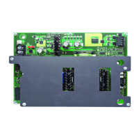
ACPS-610
ACPS-610
ACPS-610
SLC
To Next Device
on SLC
SLC
acps-610_Sync.cdr
NOTES:
• Application drawing is typical for System Sensor SpectrAlert or SpectrAlert Advance
Series horns/strobes. This application may be used for Gentex or Wheelock
electronically synchronized devices via PK-PPS programming.
• Do not “T-tap” sync riser.
• The wiring from the FACP shall be within 20 feet (6.1 m) in conduit in the same room.
• 50 ohm maximum loop resistance per sync riser. (Figure 4.4 shows one sync riser.)
• In this configuration (synchronized power supplies connected in parallel by a sync
riser), there is a maximum of 50 parallel slaves.
• For more information, see Figure 4.6.
P/N ELR-2.2K
(2.2K ohm end-
of-line resistor),
included
P/N R-2.2K
(2.2K ohm
end-of-line
resistor),
included
P/N ELR-2.2K
(2.2K ohm end-
of-line resistor),
included
S
y
n
c
R
i
s
e
r
S
y
n
c
R
i
s
e
r

 Loading...