10 APS2-6R/E Instruction Manual — P/N 53232:B 2/26/2014
Overview Board Layout
Removal of the shunt from JP4 separates the AC loss trouble from other existing troubles and works with the TB4
relay contacts for immediate trouble annunciation.
Diagnostic LEDs
LED1- Green- Indicates presence of AC power
LED2- Yellow- Illuminates when an AC or battery trouble exists
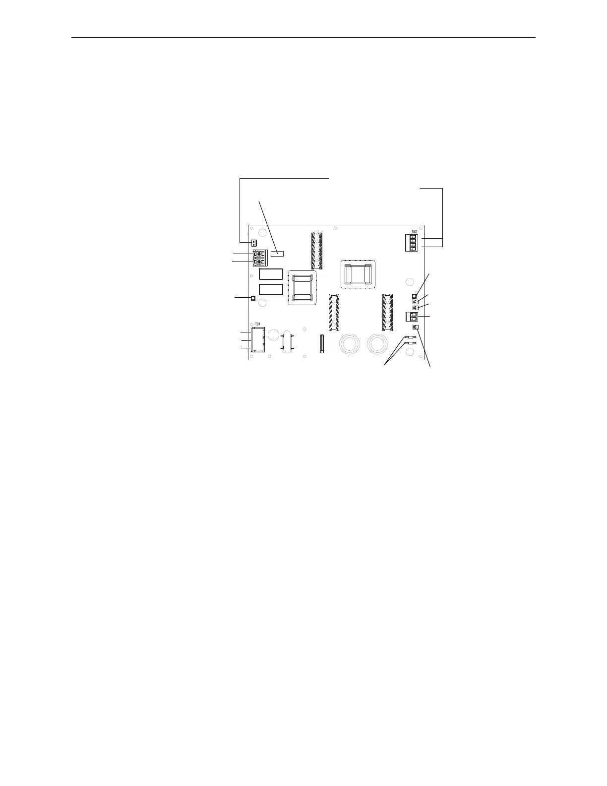
2.4 Board Layout
The figures below identify the layout of the APS2-6R power supply:
Hardware Kit
A hardware kit is included for use in assembling and mounting the APS2-6R. It consists of the following items:
Quantity Description Part No.
2 #6-32 x 1.25 in. (10 mm) long,.25
in. (2mm) hex standoff
42026
2 #6-32 self-tapping screw 38164
1 Trouble supervision cable 71033
Table 2.1 Hardware Kit Components
-
+
TB3
J9
-
+
-
+
TB4
JP4 J4
J3
JP2JP3
L
E
D
1
LED2
F
2
F
1
NOTE: The cover has been
removed for illustration
purposes only!
Three 24 VDC output circuits
One (1) non-power-limited
Two (2) power-limited
(Refer to the appropriate
appendix for more specific
information on output circuits)
Fuse F2 for battery
protection
Batt +
Batt -
Green LED-
Indicates AC
power on
AC Power
HOT
Neutral
Earth Ground
Jumpers JP2 and JP3 for selecting 1-2
hour or 2-3 hour delay for AC loss
reporting. Default is immediate. See
“Configuring the APS2-6R” on page 14.
JP4 UL 864 8th
Edition trouble
reporting
connector
TB4 AC
Fail/Brownout
Detection
See page 13 for
more information
Trouble Out (J3)
Trouble In (J4)
Yellow LED-
Indicates AC
or batt trouble
Figure 2.2 APS2-6R Board Layout