APS2-6R/E Instruction Manual — P/N 53232:B 2/26/2014 23
AM2020/AFP-1010 and System 5000 UL 864 8th Edition Configurations
7. Attach battery interconnect cable.
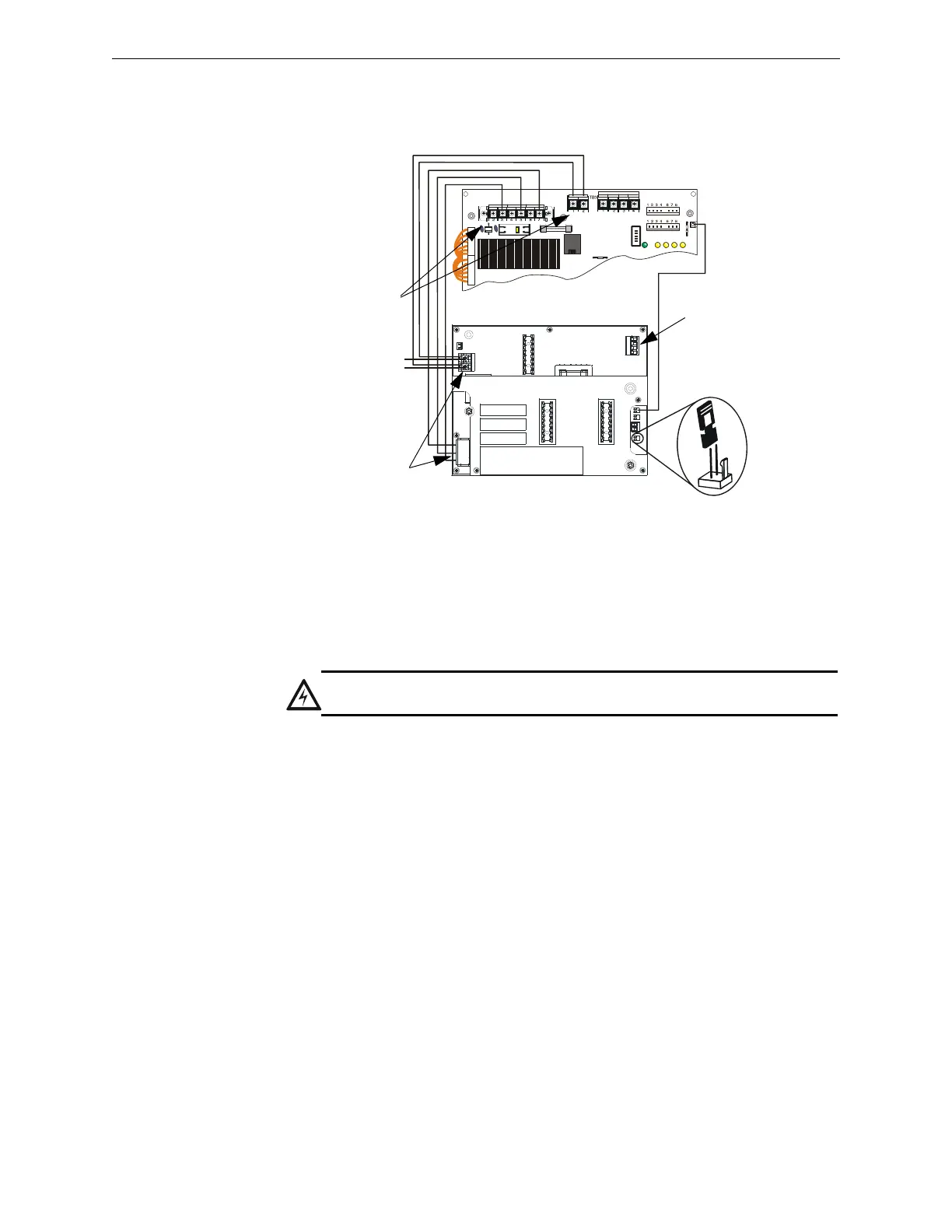
B.3.2 Connecting to an MPS-24B/RB
1. Connect trouble output from J3 on the APS2-6R to P4 on the MPS-24BRB.
2. Place shunt across both pins of JP4 on the APS2-6R.
3. Connect primary power from TB1 on the APS2-6R to MPS-24B/RB terminal block TB1, Pin 3 (
NEUT) and Pin 4
(
HOT).
4. Connect AC power to TB1 on the MPS-24B/RB. Make sure to properly ground the unit to the backbox.
5. Connect batteries to TB3 on the MPS-24B/RB.
6. Connect secondary power from TB3 on the APS2-6R to MPS-24B/RB terminal block TB3, Pin 1(+) and Pin 2(–
).
P4
P3
JP5
TB1
TB2
F1
CB1
P5
R27
P2
EARTH GND AC NEUTRAL AC HOT
+24R C OMMON +24
COMMON
POWER LIMITE D
BAT + B AT -
Note: Maintain 0.25” spacing between Power-limited and
Non-power-limited wiring. Install tie wraps and adhesive
squares to secure the wiring.
APS2-6R
to battery +
back-up -
Non-power-limited
Power-limited
aps26rtomps24a.wmf
Figure B.3 Wiring to MPS-24A
Non-power-limited
MPS-24A
WARNING:
Be sure to finish installation before applying power. Test AC power before continuing.