14 APS2-6R/E Instruction Manual — P/N 53232:B 2/26/2014
Installation Configuring the APS2-6R
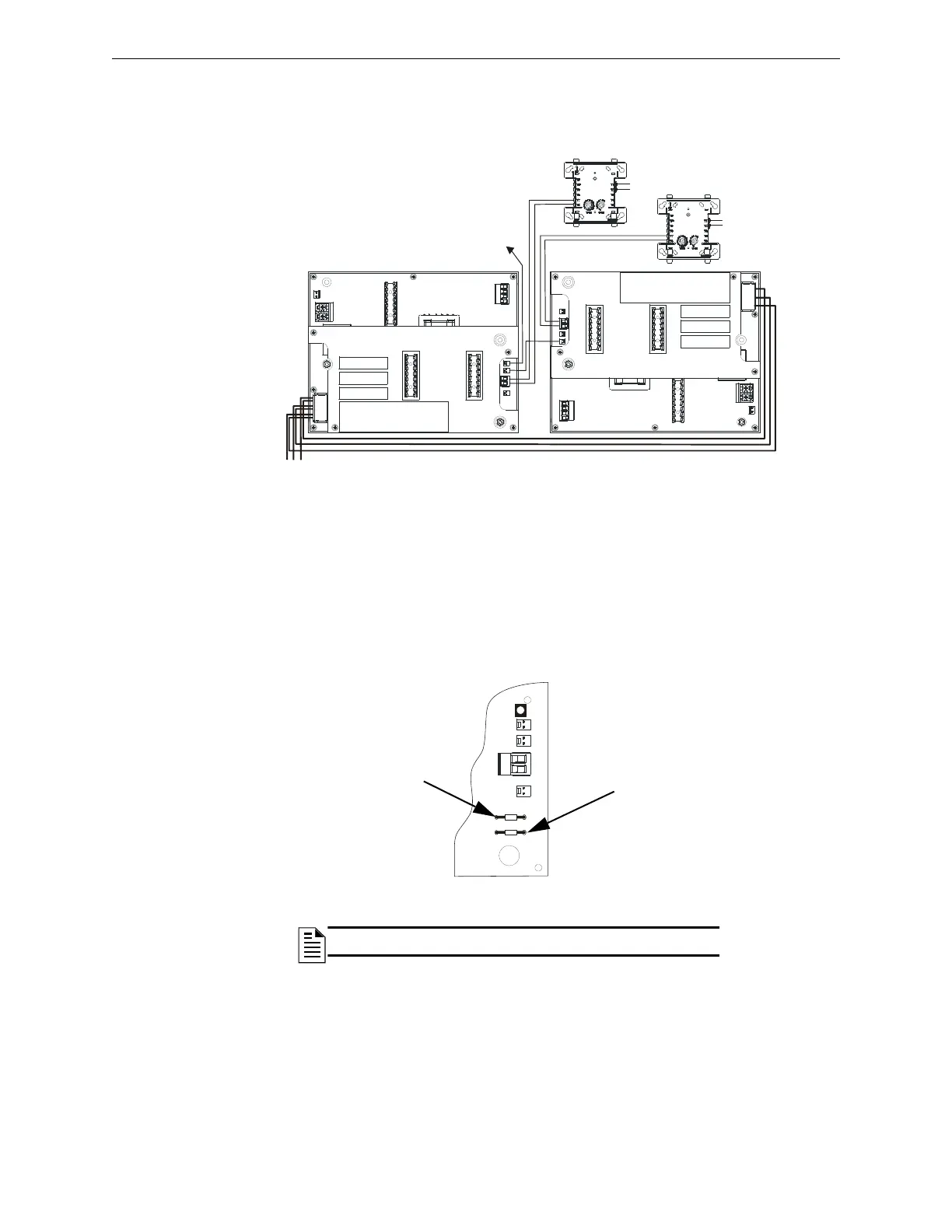
3.3.4 Connecting Multiple APS2-6R Power Supplies
The power supplies must be mounted in a CHS-4/L chassis oriented as shown in Figure 3.5 to accommodate all field
wiring. Cable #71033 must be used for all trouble bus connections. For more information on specific panel wiring,
see the appropriate appendix.
3.4 Configuring the APS2-6R
The APS2-6R may be configured for the following:
• No delay for reporting loss of AC power (default)
• 1-2 hour delay for reporting loss of AC power: cut jumper JP2.
• 2-3 hour delay for reporting loss of AC power: cut jumpers JP2 and JP3.
Figure 3.5 Wiring Multiple APS2-6R Power Supplies
To trouble input on main power
supply or control panel
First APS2-6R
Second APS2-6R
Connect power
as described in
the appropriate
appendix.
to SLC
to SLC
JP2
JP3
aps26rjump.wmf
Figure 3.6 Configuring the APS2-6R
NOTE: Refer to TB4 specifications on page 9 for more information.