APS2-6R/E Instruction Manual — P/N 53232:B 2/26/2014 13
Wiring an APS2-6R Installation
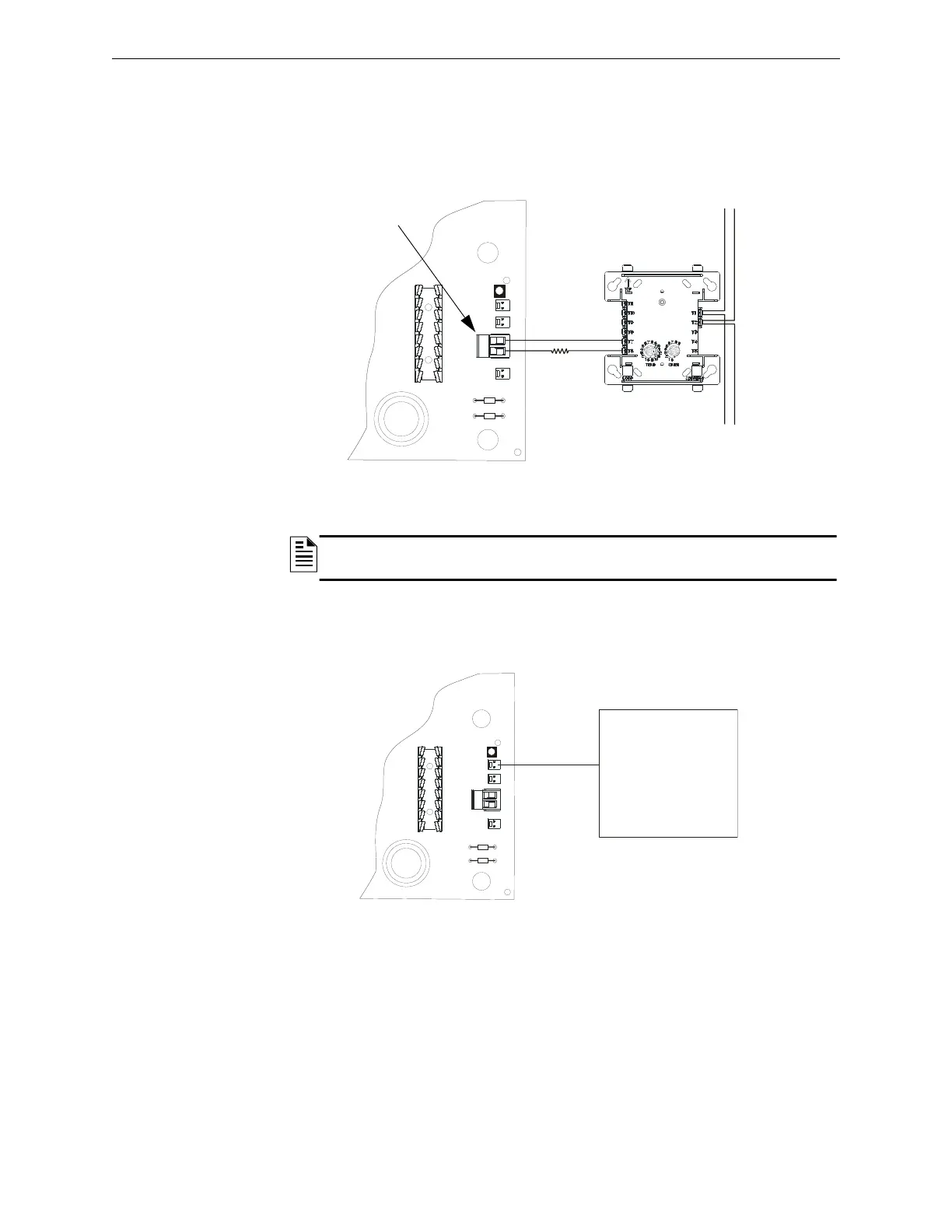
3.3.2 AC Fail/Brownout Detection
The APS2-6R monitors for power loss. In the event there is an AC failure or brownout, the APS2-6R will switch to
battery back-up. The AC Fail Relay (TB4) is monitored by an FMM-1 or equivalent monitor module on the SLC
(Signaling Line Circuit), and in this event, a trouble message will be displayed on the control panel. The monitor
module must be mounted within the same enclosure as the APS2-6R or in a closely coupled
enclosure with wiring
not exceeding 20 feet (6.1 m) in length.
3.3.3 Trouble Supervision Bus
The APS2-6R supervises battery power. If the battery voltage should drop, the APS2-6R will generate and transmit a
trouble to the control panel via trouble supervision cable #71033.
NOTE: TB4 is for UL 864 9th Edition applications only. See Appendix B for UL 864 8th Edition
applications and wiring.
aps26rtb4.wmf
AC Fail Relay
(NC)
FMM-1*
*If the SLC device does not match the one in
this figure, refer to the SLC manual appen-
dix, which contains wiring conversion charts
for type V and type H modules.
APS2-6R
SLC
Figure 3.3 Wiring for AC Fail/Brownout Detection
47K ELR
(P/N R-47K)
UL Listed,
compatible
FACP
Figure 3.4 Trouble Bus Wiring