LDM Series Instruction Manual — P/N 15885:H3 8/12/2019 53
Configuration for the LDM-32 and AFP-100 AFP-100 (UL 8th)
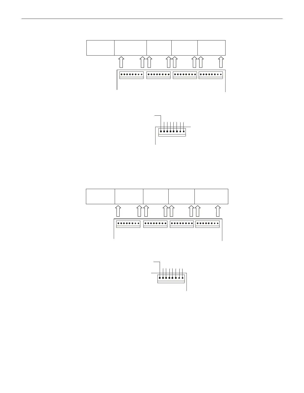
Figure D.1 illustrates configuration of the LDM to annunciate the Alarm state of all 56 software zones (no zone troubles) with the first
eight points (P1 through P8) dedicated to the AFP-100 system function LEDs listed below.
Figure D.2 illustrates configuration of the LDM to annunciate the Alarm state for up to 56 zones (no zone troubles) with the last eight
points (P57yea through P64) dedicated to the AFP-100 system function LEDs listed below.
It is assumed that the '8-Point Shift' will be selected only on systems containing less than 56 software zones or a total of 64 annunciator
points or less.
Address #1
LDM-32
LDM-E32
System Functions *
25 - 32
1 - 8
33 - 40
9 - 16
41 - 48
17 - 24
49 - 56
wire to
LEDs
* System Status Indicators
System Alarm
not used
View of LDM-32
Figure D.1 Display Alarm Status of 56 Software Zones Only Without 8-Point Shift
Address #1
LDM-32
LDM-E32
System Functions *
25 - 32
1 - 8
33 - 40
9 - 16
41 - 48
17 - 24
49 - 56
wire to
LEDs
* System Status Indicators
View of LDM-32
System Alarm
not used
Figure D.2 Alarm Status of 56 Software Zones with 8-Point Shift
 Loading...


