LDM Series Instruction Manual — P/N 15885:H3 8/12/2019 57
Configuration for the LDM-32 and AFP-100 AFP-100 (UL 8th)
Detectors
Set address ‘01’ and ‘02’ for detectors.
Modules
Set address ‘03’ and ‘04’ for modules.
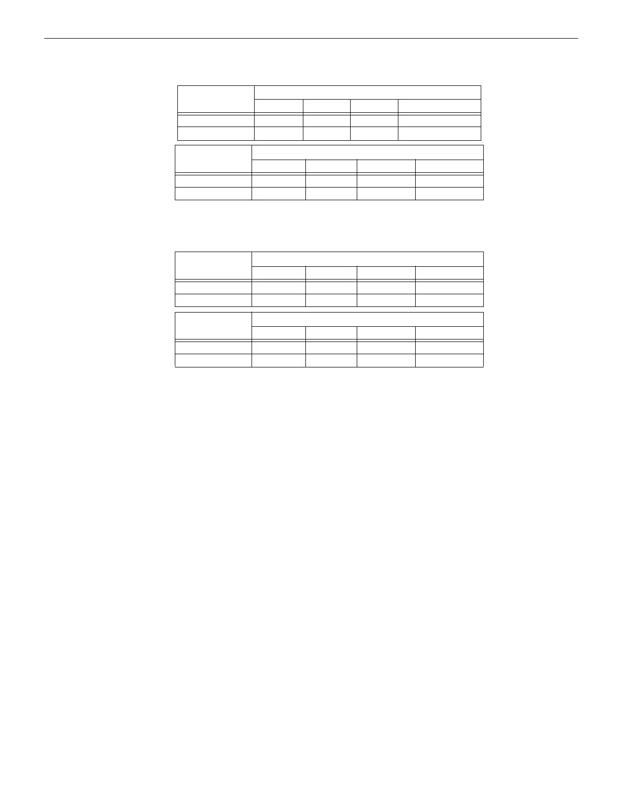
LDM Module
Address ‘01’
LDM Output Connectors
J5 J6 J7 J8
LDM-32 1 to 8 9 to 16 17 to 24 25 to 32
LDM-E32 33 to 40 41 to 48 49 to 56 System Functions
LDM Module
Address ‘02’
LDM Output Connectors
J5 J6 J7 J8
LDM-32 57 to 64 65 to 72 73 to 80 81 to 88
LDM-E32 89 to 96 97 to 99 Not used Not used
Table D.8 Alarm Only Setup - Detectors - with 8-Point Shift
LDM Module
Address ‘03’
LDM Output Connectors
J5 J6 J7 J8
LDM-32 1 to 8 9 to 16 17 to 24 25 to 32
LDM-E32 33 to 40 41 to 48 49 to 56 57 to 64
LDM Module
Address ‘04’
LDM Output Connectors
J5 J6 J7 J8
LDM-32 65 to 72 73 to 80 81 to 88 89 to 96
LDM-E32 97 to 99 Not used Not used Not used
Table D.9 Alarm Only Setup - Modules - with 8-Point Shift
 Loading...


