28 LDM Series Instruction Manual — P/N 15885:H3 8/12/2019
System 500 (UL 8th) Annunciator Operation
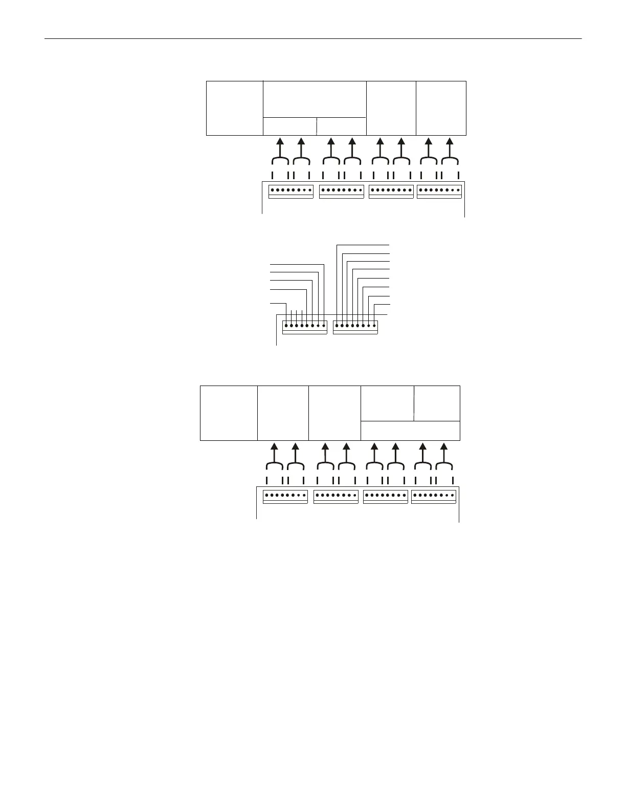
Figure A.5 illustrates the configuration of LDMs to annunciate alarms and troubles for up to 24 zones with the first eight points (J5: P1
through P8 and J6: P1 through P8) dedicated to System 500 functions.
Figure A.6 illustrates the configuration of LDMs to annunciate alarms and troubles for up to 24 zones.
J6
J5 OUTPUTS J7
J8
Alarm
Alarm Alarm Alarm
Trouble
Tro ubl e Tro ubl e
Address #1
LDM-32
1st LDM-E32
System Status Indicators *
9 - 12
13 - 16
1 - 4
17 - 20 21 - 24
5 - 8
view of LDM-32
* System Status Indicators
NAC Ckt #1 ON (Green LED)
NAC Ckt #2 ON (Green LED)
Municipal Tie ON (Red LED)
Alarm Relay ON (Red LED)
NAC Ckt #1 Trbl (Yellow LED)
NAC Ckt #2 Trbl (Yellow LED)
Municipal Tie Trbl (Yellow LED)
Alarm Relay Trbl (Yellow LED)
Supervisory (Yellow LED)
not used
Signals Silenced (Yellow LED)
System Trouble (Yellow LED)
System Alarm (Red LED)
not
used
Figure A.5 Alarm and Trouble Points Operation
J6
J5 OUTPUTS J7
J8
Alarm
Alarm Alarm Alarm
Trouble
Tro ubl e Tro ubl e
Address #1
LDM-32
1st LDM-E32
9 - 12
13 - 16
1 - 4
17 - 20
21 - 24
5 - 8
not used
Figure A.6 Alarm/Trouble Operation with 8-Point Shift
 Loading...


