30 LDM Series Instruction Manual — P/N 15885:H3 8/12/2019
System 500 (UL 8th) Annunciator Operation
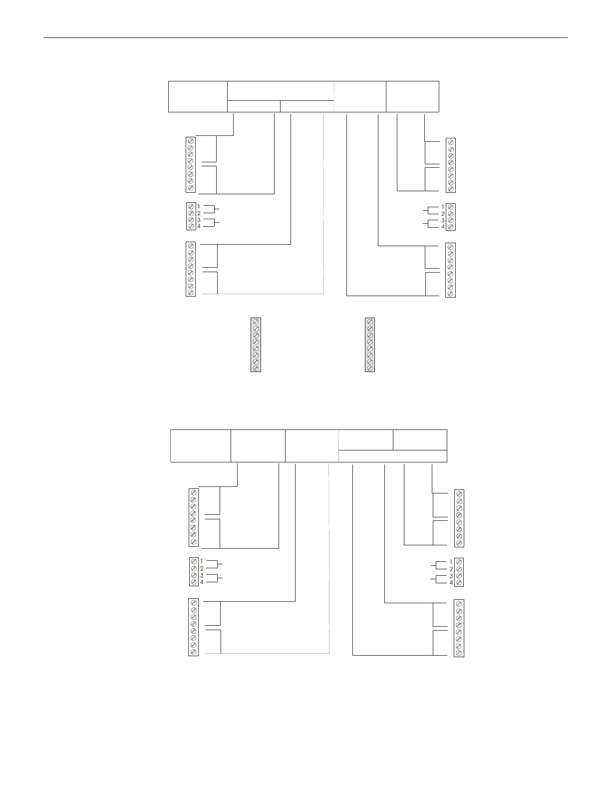
Figure A.9 illustrates the configuration of the LDM-R32 Relay Expander to activate alarm and trouble relays for up to 24 zones with the
first eight relays dedicated to the System 500 functions listed below.
Figure A.10 illustrates the configuration of the LDM-R32 to activate alarm and trouble relays for up to 24 zones.
1
2
3
4
5
6
7
8
TB3
TB4
TB5
TB2
TB6
TB1
1
2
3
4
5
6
7
8
1
2
3
4
5
6
7
8
TB2
Address #1
LDM-32
1st LDM-E32
System Status Indicators *
1 - 4 5 - 8
9 - 12
13 - 16
21 - 24
17 - 20
N.O. Contacts
N.O. Contacts
N.O. Contacts
N.O.
Contacts
Trouble
Alarm
Alarm
Trouble
Trouble
Alarm
Alarm
Trouble
Common for TB1
Common for TB2
Common
for TB3
System Alarm
not used
not used
not used
System Trouble
Signal Silenced
not used
Supervisory
NAC Circuit #1 ON
NAC Circuit #2 ON
Municipal Tie ON
Alarm Relay ON
NAC Circuit #1 Trouble
NAC Circuit #2 Trouble
Municipal Tie Trouble
Alarm Relay Trouble
* System Functions
Common
for TB4
Figure A.9 Alarm and Trouble Relays with LDM-R32
Address #1
LDM-32
1st LDM-E32
1 - 4
5 - 8
9 - 12 13 - 16
21 - 24
17 - 20
not used
N.O. Contacts
N.O. Contacts
N.O. Contacts
N.O.
Contacts
Trouble
Alarm
Alarm
Trouble
Trouble
Alarm
Alarm
Trouble
Common for TB1
Common for TB2
Common
for TB3
Common
for TB4
Figure A.10 Alarm and Trouble Relays with 8-Point Shift

 Loading...


