40 PW-7000 (PW7K1IC) Installation and Configuration Guide, Document 800-25673V1
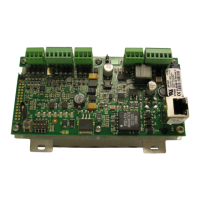
By default, Input 0 is defined as the Door Status Input corresponding to reader 0
and Input 1 is defined as the REX input corresponding to reader 0. Also by default,
Input 2 is defined as the Door Status Input corresponding to reader 1 and Input 3 is
defined as the REX input corresponding to reader 1.
Inputs 4, 5, 6 and 7 are general purpose inputs that can be used to monitor sensors
or as control inputs. Inputs 6 and 7 are not accessible when the board is rack
mounted.
Inputs TMP and PFL are typically used for monitoring cabinet tamper and power
failure respectively. These two inputs are not supervised and are not accessible
when the board is rack-mounted. These inputs were primarily provided for the case
when this board is mounted remotely and cannot take advantage of the tamper
and power fail detect inputs on the controller board. If these inputs are not used,
install a short piece of wire at the input to indicate safe condition.
Input configuration including debounce and hold time is set via host software.
Control Output Wiring
Four form-C relay contacts are provided for controlling door strike or other devices.
Each may be assigned to door-related functions or general-purpose output. They
are configurable as standard (energize to activate) or fail-safe (de-energize to acti-
vate) via host software.
The energized or ON time of each relay can be configured using Pulse control for
single or repeating pulses via host software. The energized or ON time for a single
pulse can be extended up to 24 hours. For repeating pulses, the on/off time can be
defined in 0.1 second increments and be repeated up to 255 times.
Relays 0 and 2 are rated for and normally used to control the door locks associated
with readers 0 and 1 respectively. While Relays 0 and 2 are sized to handle the typi-
cal loads generated by electrical locks, load switching can cause abnormal contact
wear and premature contact failure. Switching of inductive loads (i.e., strike) also
causes EMI (electromagnetic interference) which may interfere with normal opera-
tion of other equipment. To minimize premature contact failure and to increase
system reliability, a contact protection circuit is highly recommended. The follow-
ing two circuits are suggested. Locate the protection circuit as close to the load as
possible (within 12 inches [30cm]); the effectiveness of the circuit decreases as the
distance from the load increases.
 Loading...