Page 6 SLN 700 SmartLine NCR Level Transmitter User’s Manual Revision 1
3 Mounting
Due to the finite beam angle and resulting transmission cone, there should be no obstacles in the area
radiated by the transmitted microwave beam from the lower edge of the antenna to the material surface to
be measured. Therefore, it is necessary to avoid these facilities in the tank during installation. These
include ladders, limit switches, heating equipment, supports, etc. If necessary, some of the obstacles can
be removed from the measurement using background subtraction ("Virtual Echo Learning"). In addition,
please note that the microwave beam should not intersect with tank fluid in or out flows. Please also note
that the highest material level should not enter the near range (see Figure 3-1), the instrument should be
kept at a certain distance from the wall of tank wall and the transmitting antenna should be perpendicular
to the measured material surface as much as possible. The instruments installed in a hazardous classified
area shall follow the local national installation regulations.
The reference plane for measurement is the sealing surface of threads or flanges.
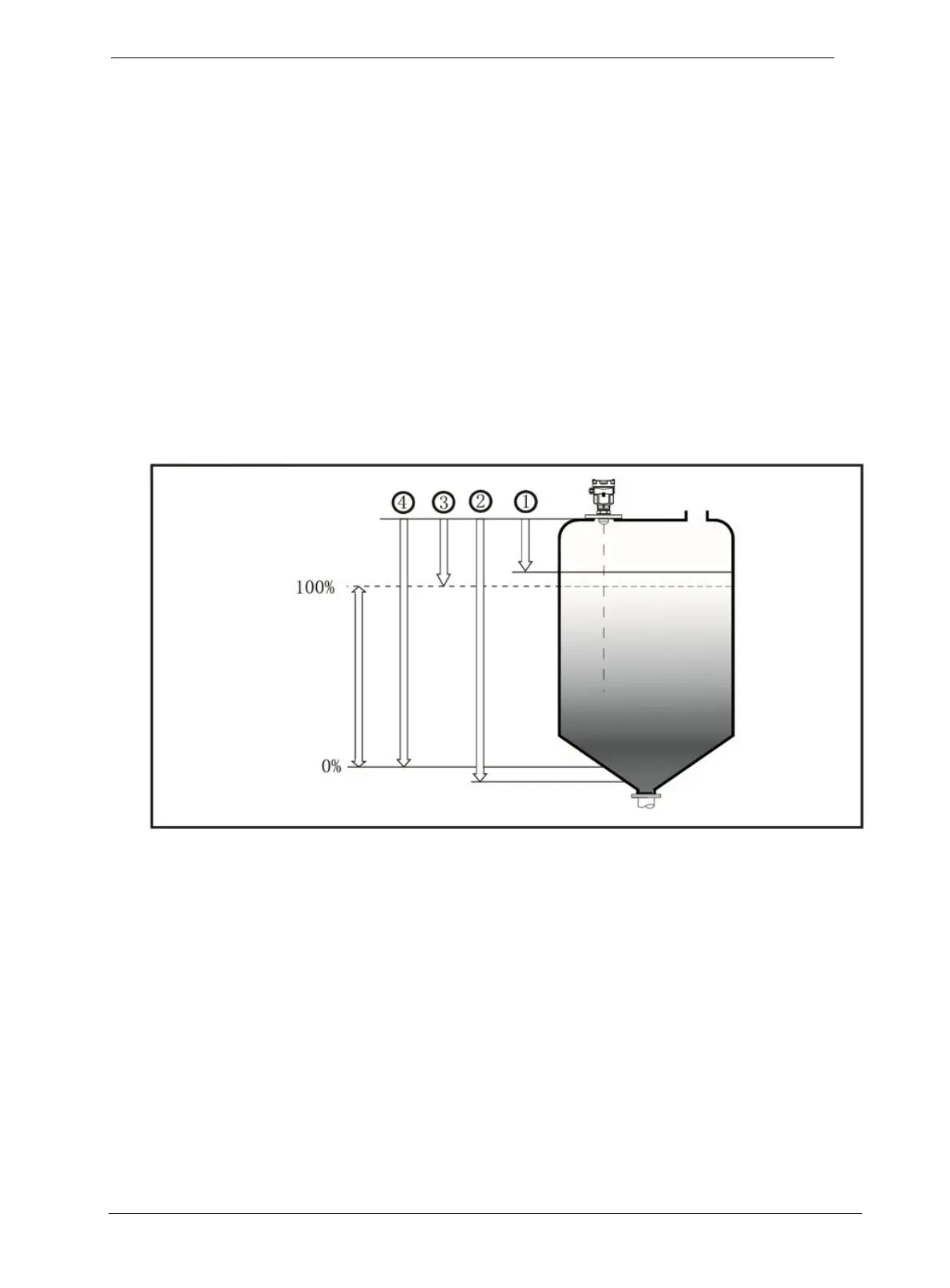
1. Near distance
2. Far distance
3. Distance at which sensor reads 100% level (or current)
4. Distance at which sensor reads 0 % level (or current)
Figure 3-1: Graphical illustration

 Loading...


