Page 8 SLN 700 SmartLine NCR Level Transmitter User’s Manual Revision 1
Installation position
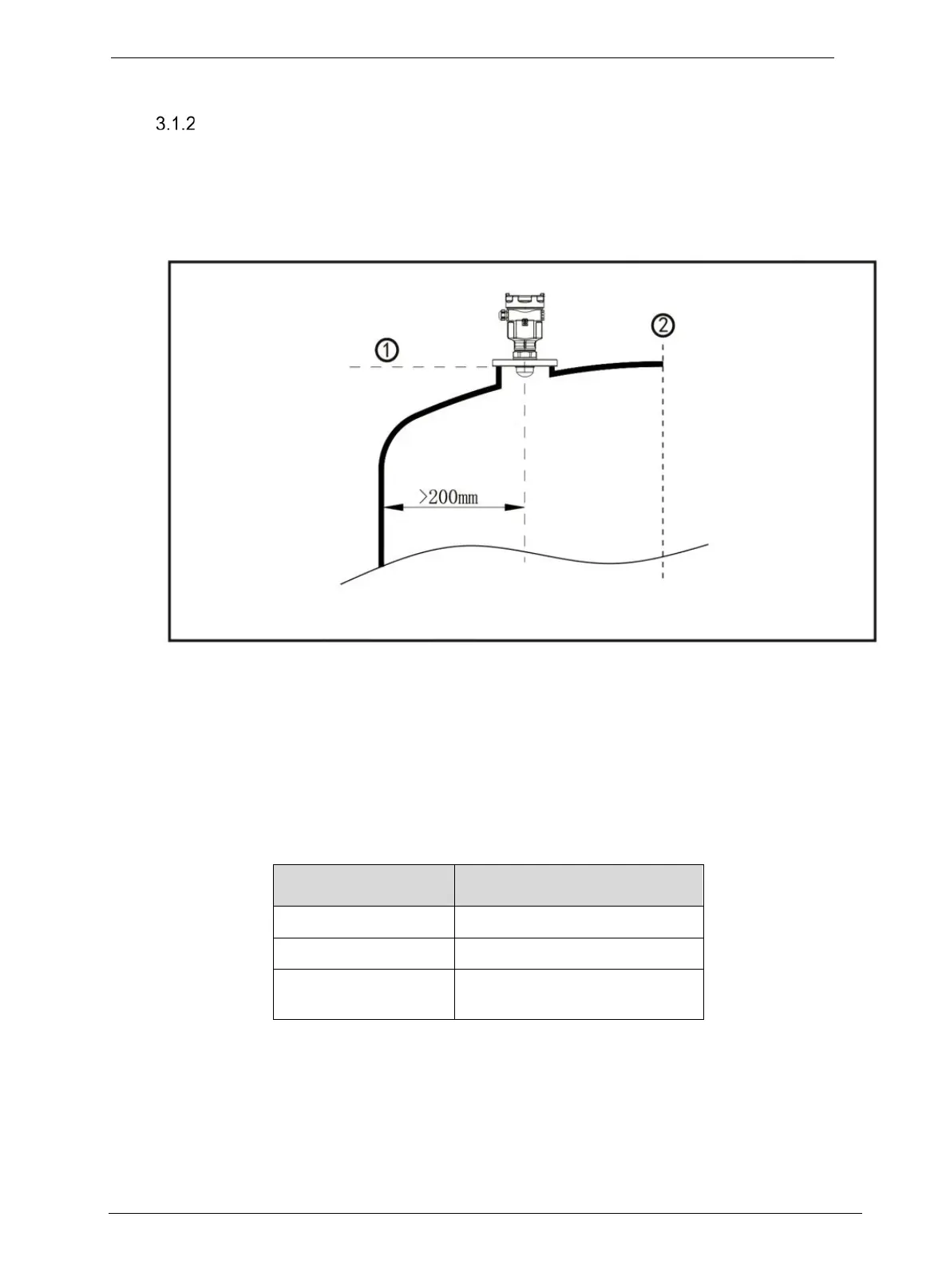
During the installation, please note that the instrument should be kept minimal distance to tank
wall from the vessel wall. For different antenna, please refer to Table 3-1.
However, the instrument must not under any circumstances be mounted closer than 200mm to
the vessel wall or values calculated from Table 3-1.
1. Reference plane
2. Center of the vessel or symmetry axis
Figure 3-3: Installation position, >200 mm
Table 3-1: Minimal distance to tank wall
SLN700 Model
Min distance to tank wall
83A 1/5 × Tank Height
82A 82B 83B 83C 1/10 × Tank Height
82C 82D 83D 83E
87A 87B 87C 87D
1/20 × Tank Height

 Loading...


