Revision 1 SLN 700 SmartLine NCR Level Transmitter User’s Manual Page 13
4 Transmitter Installation
4.1 Supply voltage
(4-20) mA / HART (2-Wire)
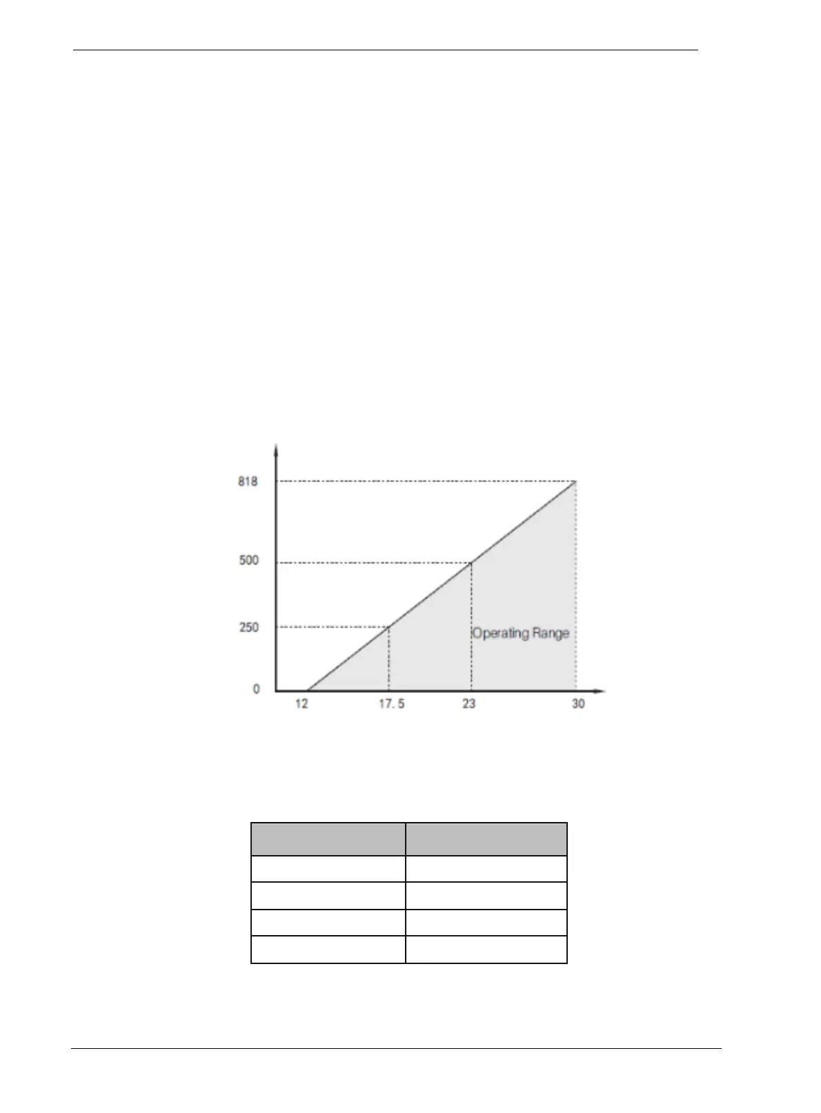
Power supply and the output current signal are carried by the same two-core cable. The allowed
supply voltage range is 12V to 30Vdepending on loop resistance. There must always be
between 12V and 30V on the transmitter terminals, regardless of loop current. A safety barrier
(refer to Table 3-1 for detailed specification) must be placed between the power supply and
instrument for the intrinsically safe version.
The grounding mode of current output can be adopted for the standard instrument, while the
floating current output should be adopted for the intrinsically safe instrument. Normally, the
grounding terminals can be connected to the grounding point of tank or an available nearby
ground in case of plastic tank.
Maximum Loop Resistance (Ω)
Figure 4-1
: Maximum Loop Resistance (Ω)
Table 4-1: Maximum Loop Resistance (Ω)
12 0
17.5 250
23 500
30 818

 Loading...


