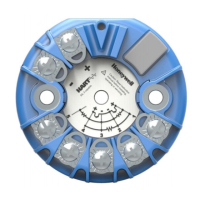
SmartLine Multivariable Transmitter
14 Quick Start Installation Guide December 2015
Figure 10: RTD Connections
o Resistance temperature detector (RTD) measurements use the
3 or 4 wire approach. The transmitter determines by itself if a 3
or 4 wire RTD is connected when powered up.
Figure 10: RTD Connections
See Figure 8, above, for parts locations.
Remove the end cap cover from the terminal block end of the
electronics housing.
Feed loop power leads through one end of the conduit
entrances on either side of the electronics housing. The
transmitter accepts up to 16 AWG wire.
Connect the positive loop power lead to the positive (+)
terminal and the negative loop power lead to the negative (-)
terminal. Note that the transmitter is not polarity-sensitive.
Feed input sensor wires through the 2
nd
conduit entrance and
connect wire.
Replace the end cap, and secure it in place.

 Loading...


